

Ask any civil engineer who has worked on an airport project and they will tell you the same thing: airports are unlike any other building type. They combine the structural complexity of a long-span industrial facility with the passenger flow logic of a transport interchange, the operational constraints of a 24-hour critical infrastructure asset, and the geotechnical unpredictability of a large-footprint site that often sits on reclaimed land, coastal margins, or former floodplain. Add to that the regulatory layer — airspace design, instrument landing system (ILS) protection zones, ICAO obstacle limitation surfaces — and you have a project environment that demands integrated thinking from the earliest stages of master planning.
This article examines real airports examples from across the world, drawing out the engineering principles, structural decisions, and project delivery lessons that practitioners and students can apply directly. From greenfield mega-projects in the Gulf to terminal expansions at constrained urban sites in the UK, the examples here illustrate how sound civil and structural engineering translates airport ambition into operational reality.
Airport engineering examples span greenfield terminals, runway extensions, underground transit stations, and phased expansions at live sites. Each type presents distinct structural, geotechnical, and systems challenges. Major recent examples include Hamad International in Qatar, Heathrow Terminal 2 in the UK, and the ongoing expansion of Lagos and Abuja airports in Nigeria — each demonstrating how master planning, procurement, and technical integration determine long-term performance.

What Makes Airport Engineering Distinct
Airport engineering is the discipline concerned with planning, designing, and constructing the physical infrastructure that enables safe and efficient air travel. It encompasses airfield civil works — runways, taxiways, aprons, and drainage — alongside terminal buildings, passenger processing facilities, ground transport connections, utilities, and the complex systems that tie all of these elements together.
The scale ranges enormously. A domestic aerodrome serving a regional Nigerian city — say, Akure or Calabar — may involve a single runway of 2,400 m, a modest terminal building of 3,000 m², and a simple parallel taxiway. A hub airport like Murtala Muhammed International in Lagos serves tens of millions of passengers per year across multiple terminals, with a runway pavement structure designed for Code E wide-body aircraft and an apron capable of parking over a hundred aircraft simultaneously. The engineering principles are the same; the complexity is not.
What distinguishes airport projects from most other civil engineering works is the intersection of three constraints that rarely appear together at this intensity: airspace geometry, which controls the height, position, and shape of every above-ground structure within several kilometres of the runway threshold; live operations, which mean that most airport projects must be designed and delivered without ever shutting the airport down; and multi-system integration, where structural, mechanical, electrical, IT, and aviation systems must all be designed to work together and handed over as a single operational package.
The Federal Airports Authority of Nigeria (FAAN) governs airport design and operations within Nigeria, applying ICAO Annex 14 standards for aerodrome design alongside local infrastructure requirements. In the UK, the Civil Aviation Authority (CAA) enforces compliance with CAP 168 (Licensing of Aerodromes) and the relevant Eurocodes as adopted for aviation infrastructure. In the UAE, the General Civil Aviation Authority (GCAA) oversees aerodrome standards across Dubai International and Abu Dhabi airports. Understanding which regulatory body governs a project is not an administrative detail — it determines the design standards, approval process, and the certification pathway for new infrastructure.
For a foundational understanding of how airports fit within the broader civil infrastructure landscape, the airports engineering guide on StruviaCore covers the key planning and design principles from inception through handover.
Greenfield Airport Examples: Building from Scratch
Greenfield airport projects — those built on a site with no existing aviation infrastructure — offer the clearest illustration of the full airport engineering process. Without the constraint of working around live operations, design teams can optimise geometry, structure, and systems from the ground up. In practice, even greenfield sites carry significant constraints: ground conditions, flood risk, airspace conflicts with nearby aerodromes, and resettlement of existing land uses.
Hamad International Airport, Doha, Qatar
Hamad International Airport (HIA), which replaced the old Doha International Airport in 2014, is one of the most extensively studied greenfield airport examples of the past two decades. The airport sits on approximately 29 km² of reclaimed land on the eastern coast of Qatar, with two parallel runways — each 4,850 m long — oriented north-east to south-west to accommodate the prevailing wind direction while maintaining separation from Doha’s urban airspace.
The reclamation itself presented the first major geotechnical challenge. The Qatar coastline is underlain by calcarenite — a weak, porous carbonate rock — overlain by variable thicknesses of marine sediment and hydraulic fill. The terminal building, which covers approximately 600,000 m² of gross floor area, is founded on a combination of driven piles and raft foundations, with pile lengths ranging from 25 m to 45 m depending on local stratigraphy. Differential settlement between the central terminal block and the satellite concourses — linked by an underground automated people mover — was a governing design consideration, with post-construction settlement monitoring targets set at less than 25 mm total and 10 mm differential over a ten-year period.
The terminal roof structure at HIA is a steel space frame spanning up to 90 m between columns in the central arrivals and departures hall. Steel was the only viable material for spans of this length given the programme constraints and the need to prefabricate elements off-site in Europe and the Far East before shipping to Qatar. The space frame was erected using a jack-and-slide method: individual sections were assembled at grade on temporary supports, then jacked to final height in a coordinated sequence to control the redistribution of loads during erection. This method eliminated the need for high-level working at altitude across the full roof area — a meaningful safety benefit on a site with a peak workforce exceeding 40,000 workers.
Beijing Daxing International Airport, China
Beijing Daxing International Airport (PKX), which opened in September 2019, represents the largest single-phase airport construction project completed in the 21st century to date. The terminal building — designed by Zaha Hadid Architects with ADPI as airport planner — covers approximately 700,000 m² and is served by six runways, though only four were operational at opening. The building sits on a foundation system of approximately 63,000 concrete piles, driven to depths of up to 30 m through the soft alluvial soils of the North China Plain.
The Daxing project is instructive for one specific reason beyond its scale: the integration of high-speed rail directly beneath the terminal building. The Beijing–Xiong’an intercity railway and the Beijing–Hong Kong high-speed line both pass through a purpose-built below-grade station directly under the terminal’s central hub. The rail tunnels run at approximately 17 m below the terminal floor level, separated from the terminal foundation system by a structural transition zone designed to accommodate differential settlement between the rail infrastructure and the terminal superstructure. Track-structure interaction analysis — accounting for temperature-induced rail forces, train braking loads, and long-term creep — was a critical input to the foundation design for the columns immediately above the tunnels.
The lesson from Daxing is that integrating high-speed rail into a terminal from the outset, rather than retrofitting it later, produces a vastly better result for passengers and a more manageable structural challenge for engineers. This principle is directly relevant to ongoing airport development in Nigeria, where both Murtala Muhammed International in Lagos and Nnamdi Azikiwe International in Abuja have long-term master plans that include rail connections — connections that will be far more expensive and disruptive if deferred until after terminal expansion is complete.

Airport Expansion Examples at Live, Constrained Sites
The majority of airport engineering work globally is not greenfield construction. It is the modification, expansion, and upgrade of existing airports that continue to operate throughout the works. This is where airport engineering becomes genuinely difficult — and where the most transferable lessons lie.
Heathrow Terminal 2: The Queen’s Terminal, London
The replacement of Heathrow’s original Terminal 2 — opened in 1955 and progressively expanded until its closure in 2009 — with the new Terminal 2 (T2) complex is one of the most carefully managed airport decant and construction programmes in UK history. The new T2 opened in June 2014 and serves Star Alliance airlines. It comprises a main terminal building (T2A) of approximately 250,000 m² and a satellite concourse (T2B) connected by an underground automated people mover tunnel.
The structural challenge at T2 centred on two issues. First, the terminal sits immediately adjacent to the live Heathrow Express and London Underground Piccadilly Line tunnels, which run through the central area of the airport at shallow depth. The new terminal foundations had to be designed to avoid imposing additional loading on the tunnel linings — this restricted the use of driven piles near the tunnel zone and required the use of continuous flight auger (CFA) piles installed with low-vibration techniques, with pile positions set back a minimum of 3 m from the tunnel extrados. All piling works within 15 m of the tunnel centrelines required approval from London Underground Limited under the Party Wall Act equivalent provisions for underground structures.
Second, the phased demolition of the old terminal and construction of the new one had to be sequenced around the continued operation of the adjacent Terminal 1 — which handled tens of millions of passengers per year until its own closure in 2015. Temporary hoarding, traffic management, and airside vehicle routing plans changed on a monthly basis as the construction programme advanced. The Principal Contractor maintained a live interface register of over 300 active interfaces between the T2 construction programme and Heathrow Airport’s operational teams at any given time.
The T2 project also used Building Information Modelling (BIM) at Level 2 — at the time, one of the most advanced BIM deployments on a UK airport project. The federated model integrated structural, architectural, mechanical, electrical, and public health (MEP) models from over 30 subcontractors, enabling clash detection to be resolved in the model rather than on site. The reduction in construction-phase Requests for Information (RFIs) attributable to pre-construction clash detection was estimated at over 30% compared to the T1 and T4 expansion projects that preceded T2. For practitioners working on complex multi-discipline airport projects, the structural engineering guide on StruviaCore provides further context on managing structural interfaces in complex building programmes.
Murtala Muhammed International Airport, Lagos — Terminal Expansion Context
Nigeria’s busiest airport presents a different category of challenge: expansion under severe infrastructure constraint, in a tropical climate, on a site where subsurface conditions vary significantly across short distances. The international terminal at MMIA — known as the MMA1 facility — dates largely from the 1970s and has been subject to incremental expansion and refurbishment rather than wholesale redevelopment.
The apron pavement at MMIA illustrates a recurring challenge at Nigerian airports. The subgrade soils across much of the Lagos airport site are lateritic clays and sandy clays with California Bearing Ratio (CBR) values typically in the range of 3–8% at formation level — too weak for direct pavement construction to Code F (for aircraft such as the Boeing 747-8 or Airbus A380). Pavement design follows ICAO Airport Services Manual Part 3 and the UK CAA’s advisory material, with subbase and base courses sized to achieve an equivalent CBR of 15% or better at sub-base level before granular base construction begins. Where CBR values fall below 3% — which occurs in areas of seasonal waterlogging near the drainage channels crossing the site — ground improvement by dynamic compaction or lime stabilisation is required before pavement construction can start.
The broader pattern of airport infrastructure investment across Nigeria — at Abuja, Port Harcourt International, and the new Lekki Airport project in Lagos State — reflects the same engineering realities: tropical ground conditions requiring site-specific geotechnical investigation, high rainfall intensity requiring robust surface drainage design per the Nigerian Urban and Regional Planning Act provisions, and structural designs that account for the high ambient humidity and temperature cycling that accelerates corrosion of steel and concrete alike. These are not obstacles unique to Nigeria; they are the standard condition for airport engineering across sub-Saharan Africa and much of Southeast Asia.
Understanding the urban infrastructure context in which airports operate — including their relationship to road networks, utilities, and city master plans — is essential for any engineer working on airport expansion. The urban infrastructure guide on StruviaCore provides the broader planning framework within which airport projects sit.
Common Engineering Challenges Across Airport Examples
Across the examples above, five engineering challenges recur with sufficient consistency that they merit explicit treatment. Any engineer preparing for an airport project — at any scale — should expect to encounter them.
Long-span roof structures and column-free spaces. Terminals require large column-free areas for check-in halls, gate lounges, and baggage reclaim. Spans of 40–90 m are common in international terminals. Steel space frames, cable-stayed roofs, and glulam timber structures have all been used successfully. The governing design actions are wind uplift (often the critical load case on lightweight roofs), differential temperature between the external roof surface and the internal structure, and dynamic response to crowd-induced vibration in areas where large numbers of passengers gather. BS EN 1990 and BS EN 1991 provide the Eurocode framework for load combination and structural performance verification in the UK; in Nigeria, BS codes as adopted by the Standards Organisation of Nigeria (SON) apply alongside COREN’s professional oversight.
Apron pavement design for mixed aircraft types. Modern airports serve aircraft from regional turboprops weighing 20 tonnes to wide-body freighters exceeding 600 tonnes MTOW. The apron pavement must accommodate this full range, and the pavement classification number (PCN) — the ICAO metric for pavement bearing capacity — must be determined accurately and communicated to airlines. Under-declaring PCN creates operational restrictions; over-declaring it risks pavement failure. Pavement design uses either flexible (asphalt) or rigid (concrete) construction, with rigid concrete preferred on stands where aircraft park stationary for extended periods, as creep under sustained load is less of a concern than under wheeling traffic.
Drainage design for airfield surfaces. Runway and taxiway surfaces must drain rapidly to prevent standing water, which creates aquaplaning risk during take-off and landing. Design rainfall intensities for airfield drainage follow ICAO Annex 14 guidance, with local intensity-duration-frequency (IDF) data informing the hydraulic design. In Lagos, design rainfall intensities for a 1-in-10-year storm at 15 minutes duration can reach 120–140 mm/hour — among the highest in the world — requiring large-capacity surface channels and inlet structures that would be considered oversized in a UK context. Drainage outfalls from aircraft stands must incorporate oil-water separators and, on stands where fuel uplift occurs, spill containment bunds to prevent hydrocarbons reaching the drainage network.
ILS critical area protection during construction. The Instrument Landing System (ILS) — which guides aircraft to the runway threshold in low-visibility conditions — is highly sensitive to interference from large structures or moving vehicles within defined critical and sensitive areas on either side of the runway centreline. Any construction activity within these areas requires formal coordination with the Air Navigation Service Provider (in Nigeria, the Nigerian Airspace Management Agency, NAMA) and may trigger temporary ILS outages or weather minima restrictions. Construction programmes must account for these restrictions: a tower crane positioned within the ILS critical area can ground all IFR traffic during construction operations, at significant cost to the airport and airlines.
Programme management across multiple concurrent packages. Large airport projects are almost never delivered by a single contractor under a single contract. They are split into multiple packages — civil and structural works, MEP services, specialist systems (baggage handling, check-in technology, security screening), airfield works, and fitout — each with its own contractor and programme. The interface management burden falls on the client’s project management team, or on a Management Contractor or Programme Manager appointed for that purpose. Without a single integrated master programme and a defined interface management process, package interfaces become the principal source of delays and claims. The transportation engineering guide on StruviaCore addresses multi-package programme management in the context of major infrastructure delivery.
Best Practices Drawn from Airport Engineering Examples
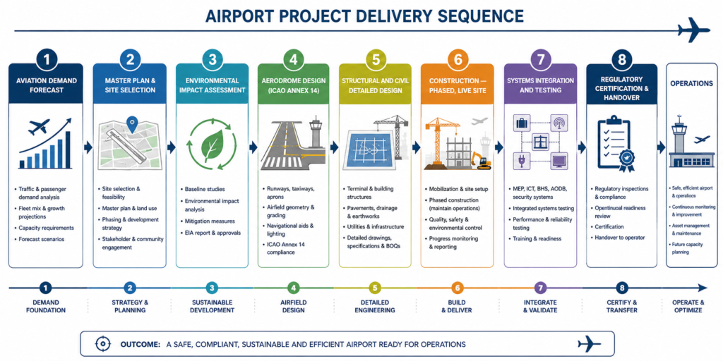
The following practices are not theoretical ideals — they are drawn directly from the lessons that well-delivered airport projects demonstrate and that poorly delivered ones ignore. Apply them from master planning stage, not from contract award.
- Fix the airfield geometry before designing any terminal or landside structure. Runway centreline, threshold position, taxiway layout, and obstacle limitation surfaces govern the position, height, and footprint of every above-ground element on the site. Changing the runway geometry after terminal design has begun is extraordinarily expensive and may be impossible without demolishing completed structures.
- Conduct a site-specific geotechnical investigation at sufficient density before pavement or foundation design begins. For runway and apron pavements, a minimum of one borehole or trial pit per 2,000 m² of pavement area is a reasonable starting density; for terminal foundation design, one borehole per major column grid intersection. Do not rely on regional soil maps or adjacent site records — airport sites are large and variable.
- Integrate the airside drainage design with the wider catchment hydrology. Airport drainage cannot be designed in isolation. The site sits within a wider catchment and must not increase peak runoff to receiving watercourses. Sustainable drainage system (SuDS) principles apply at airports as at any other development, modified for the contaminant risk from fuel spills and de-icing fluid.
- Appoint a Building Information Modelling (BIM) manager and establish a Common Data Environment (CDE) before any design package begins. Airport projects involve too many disciplines and too many contractors to manage on 2D drawings. A federated BIM model, maintained throughout design and construction, reduces RFIs, accelerates clash detection, and provides the as-built record the airport operator needs for facilities management after handover.
- Engage NAMA, FAAN, the CAA, or the GCAA — whichever applies — from the earliest stage of design. Regulatory approvals for aerodrome works take longer than most clients expect. ILS flight calibration after any airfield infrastructure change requires a specialist flight calibration sortie and can take weeks to schedule. Building these lead times into the programme from day one avoids last-minute delays to operational handover.
- Design for future phases, not just the current one. The terminal you design today will be expanded within 15–20 years if the aviation demand forecast is correct. Foundation systems, structural grids, MEP risers, and airside road layouts should all be designed with known future phases in mind. The incremental cost of providing structural provisions for future expansion at initial construction is typically 5–10% of the affected element cost; the cost of retrofitting is three to five times that.
- Plan construction logistics around airside access constraints from day one. All vehicles operating airside require permits, driver training, and Foreign Object Debris (FOD) inspections. Deliveries must use designated Vehicle Service Roads that cross the airside boundary at controlled points. This is not a minor inconvenience — it fundamentally affects construction methodology, plant selection, and materials delivery scheduling. Contractors unfamiliar with airport working environments consistently under-programme these logistics constraints.
- Verify PCN assignments for all pavement areas before handover, using deflection testing. Plate bearing tests or Falling Weight Deflectometer (FWD) measurements should confirm the as-built pavement performance against the design PCN. Airlines and ground handlers will not accept a declared PCN without supporting data, and FAAN, the CAA, and GCAA all require certified pavement strength data as a condition of aerodrome licensing.
Airport projects that integrate rail connections — whether an automated people mover on campus or a mainline rail link to the city — face an additional layer of complexity. The rail engineering guide on StruviaCore addresses the track-structure, signalling, and systems integration requirements that airport rail connections demand.
Frequently Asked Questions About Airports
Q: What is the difference between a Code C and a Code E airport in ICAO terms?
A: ICAO Annex 14 classifies aerodrome reference codes by a letter (A–F) based on the wingspan and outer main gear wheel span of the critical aircraft the airport is designed to serve. Code C covers aircraft with wingspans of 24–36 m — such as the Boeing 737 or Airbus A320 family — and requires a taxiway width of 18 m with 4.5 m clearances. Code E covers aircraft with wingspans of 52–65 m — including the Boeing 777 and 787 — and requires taxiway widths of 23 m with 7.5 m clearances. The code designation directly affects pavement width, apron stand dimensions, obstacle limitation surfaces, and the structural design loads for airside infrastructure including bridges and underpasses carrying taxiway loads.
Q: How long does it take to deliver a new international terminal building?
A: For a mid-size international terminal of 60,000–120,000 m² gross floor area, the typical programme from project inception to first passenger operation is 6–9 years: approximately 1–2 years for master planning, demand forecasting, and site investigations; 1–2 years for detailed design, environmental impact assessment, and regulatory approvals; 3–4 years for construction; and 12–18 months for systems installation, testing, and commissioning. Programmes are most commonly extended by planning and environmental approvals, scope changes during construction, and delays in systems integration testing. Major hub terminals — such as those at Doha or Beijing Daxing — required 8–12 years from concept to opening.
Q: What are the main geotechnical risks on airport construction sites?
A: The most significant geotechnical risks on airport sites are variable subgrade conditions beneath large pavement areas (leading to differential settlement and pavement cracking), high groundwater tables requiring dewatering during substructure construction, shrink-swell behaviour in tropical lateritic clays under seasonal wetting and drying cycles, and — on reclaimed or coastal sites — consolidation settlement of marine sediments under the weight of new fill and structures. A phased geotechnical investigation at adequate density, combined with a ground risk register updated throughout design and construction, is the standard risk management response. In Nigeria, where laterite profiles can change significantly over short distances, investigation density greater than the minimum is often justified.
Q: What is an ILS critical area, and why does it matter for construction planning?
A: The Instrument Landing System (ILS) critical area is a defined zone around the localiser and glidepath antennas within which the presence of vehicles, structures, or aircraft can cause reflections that corrupt the ILS signal and give pilots inaccurate approach guidance. ICAO Doc 9365 defines the critical area dimensions for each ILS category (CAT I, II, III). Any construction work within this zone — including tower cranes, temporary buildings, or stockpiles — must be coordinated with the Air Navigation Service Provider (NAMA in Nigeria) and may require the ILS to be taken out of service or downgraded to a lower CAT during the works. Failure to manage this correctly can result in flight cancellations and regulatory enforcement action against the airport operator.
Airports Examples: The Engineering Principles That Endure
The airports examples examined here — from the reclaimed coastline of Qatar to the lateritic soils of Lagos, from the constrained tunnelled environment beneath Heathrow to the high-speed rail integration at Beijing Daxing — share a common engineering logic. Scale changes. Materials change. The regulatory framework changes with geography. But the principles do not: investigate the ground thoroughly before you commit to a foundation system; fix the airfield geometry before designing the buildings around it; design for the next phase while you are building the current one; and manage the interfaces between packages with the same rigour you apply to the structural design itself.
Airports examples are among the richest sources of civil and structural engineering lessons available, precisely because the consequences of getting the engineering wrong are so immediate and so visible. A terminal that floods because its drainage was undersized, a pavement that fails because its PCN was overstated, a construction programme that slips because ILS restrictions were not planned for — these outcomes are measured in flight cancellations, airline penalties, and national economic cost.
StruviaCore works with clients across the airport infrastructure spectrum — from feasibility and master planning through to detailed design and construction support. If you are developing airport infrastructure and need independent technical input on structural design, geotechnical risk, or project delivery strategy, contact our team. You can also explore related technical resources, including the urban infrastructure guide, to understand how airport projects interact with the wider built environment.
Leave a Reply