

Designing and building in the marine environment is unlike any other construction context. The sea does not forgive errors in material specification, foundation assumptions, or drainage philosophy. A port wharf that performs adequately in calm harbour conditions can face catastrophic scour during a storm surge; a jetty pile that passes visual inspection above the waterline may be losing 3–5mm of section thickness per year to accelerated low-water corrosion (ALWC) below the tidal zone. Engineers working in the marine sector — whether on river crossing structures, coastal protection works, offshore berths, or tidal barrages — encounter a convergence of structural, geotechnical, hydraulic, and materials challenges that rarely present in isolation.
This article examines the primary marine infrastructure challenges that practitioners face across the full asset lifecycle, from site investigation and foundation design through to construction logistics, corrosion management, and long-term maintenance. It covers the technical realities behind each challenge, the standards and codes that govern engineering responses, and the practical decisions that separate durable marine assets from costly failures.
Marine infrastructure challenges arise from the combined action of corrosive saltwater, dynamic wave and tidal loading, unpredictable seabed conditions, and extreme construction access constraints. Engineers address these through marine-grade material specifications, specialist geotechnical investigation, hydraulic modelling, and phased maintenance regimes referenced to standards such as BS 6349 and ISO 12944.
What Is Marine Infrastructure and Why Is It Uniquely Demanding
Marine infrastructure is the collective term for engineered structures and systems constructed in, over, or adjacent to tidal, estuarial, coastal, or offshore water environments. It encompasses port and harbour facilities — quay walls, jetties, dolphins, dry docks — as well as coastal flood defences, tidal barrages, undersea pipelines, submarine cable installations, offshore platform foundations, and river training works. The full scope of what constitutes marine infrastructure extends well beyond the visible waterfront; it includes the submerged and buried elements that carry structural load, resist hydraulic forces, and maintain serviceability over design lives that routinely exceed 50 years.
What makes this environment uniquely demanding is the simultaneous presence of multiple degradation mechanisms and loading conditions that do not combine linearly. Structural steel loses section to corrosion while simultaneously carrying cyclic wave loads. Concrete piles are subject to chloride ingress in the splash zone while the same member resists lateral pressures from berthing vessels. A sheet pile retaining wall must hold back saturated fill while groundwater chemistry accelerates the electrochemical corrosion of the steel itself. In reinforced concrete structures built without adequate cover to BS 6349-1:2000 (now superseded by BS EN 1992 applied with marine exposure class XS3), chloride-initiated corrosion of reinforcement can reduce structural capacity by 20–40% within 15–25 years, depending on tidal exposure and concrete permeability.
The regulatory and standards landscape adds further complexity. In the UK, BS 6349 (Maritime Structures) remains a key reference series alongside the Eurocodes as adopted, particularly BS EN 1997 for geotechnical design and BS EN 1992 / BS EN 1993 for concrete and steel member design. Internationally, the PIANC (Permanent International Association of Navigation Congresses) guidelines are widely referenced for port and waterway works. Projects in Nigeria must satisfy COREN registration requirements and increasingly align with NIS ISO standards as adopted locally; marine terminals operated by the Nigerian Ports Authority (NPA) reference BS 6349 and PIANC for design verification on major capital works.
The Marine Exposure Classification System
BS EN 206 and BS EN 1992 classify marine exposure in three sub-classes relevant to reinforced concrete design: XS1 (airborne salt, no direct contact), XS2 (permanently submerged), and XS3 (tidal, splash, and spray zones). XS3 governs the most aggressive conditions and demands a minimum concrete cover of 50–55mm to primary reinforcement for a 50-year design life, rising to 60–65mm for a 100-year design life. Getting this specification right at the design stage has major cost implications; retrofitting inadequate cover through cathodic protection or patch repair typically costs three to five times more than specifying correctly at the outset.
Foundation Conditions in the Marine Zone
Seabed and nearshore geology does not follow the predictable stratigraphy of a greenfield development site. Estuarial deposits often present interbedded soft alluvial clays, loose sands, and organic material (peat lenses) that shift with tidal drawdown and storm events. Scour — the erosion of seabed material around foundation elements under tidal and wave-induced flow — is responsible for a disproportionate share of marine structure failures. Scour depths at exposed bridge piers and jetty piles can reach 2–3 times the pile diameter under design storm conditions if protection is inadequate. BS 6349-5 addresses moorings, and specialist geotechnical guidance for scour assessment references the Highways England (now National Highways) BD 97 series as cross-sector guidance even in non-highway contexts.
Corrosion: The Dominant Materials Challenge in Marine Infrastructure
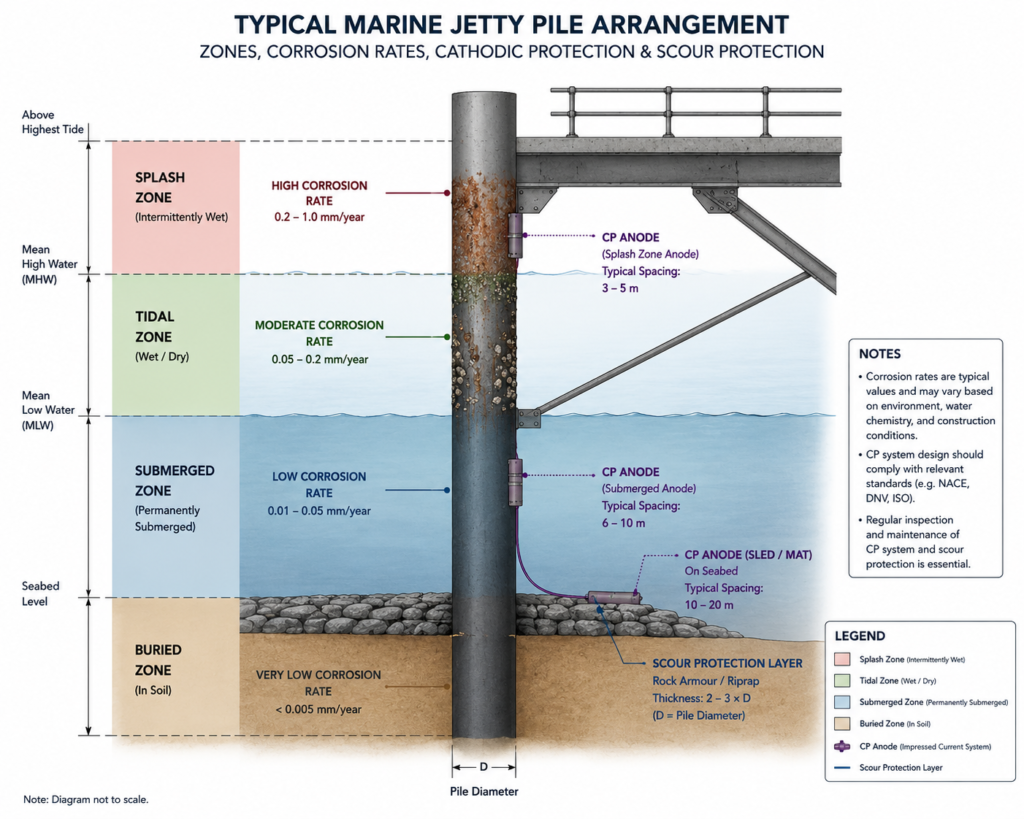
Corrosion is the defining materials challenge across all marine infrastructure challenges. Steel — whether in tubular piles, sheet piling, reinforcement bars, or structural connections — corrodes at rates in the marine environment that are two to three orders of magnitude greater than in typical inland atmospheric exposure. Unprotected mild steel in a temperate tidal zone loses approximately 0.1–0.3mm per year from general atmospheric corrosion, but accelerated low-water corrosion (ALWC) — the electrochemical-bacterial process concentrated at and just below the mean low water mark — can produce section loss of 1–3mm per year in severe cases.
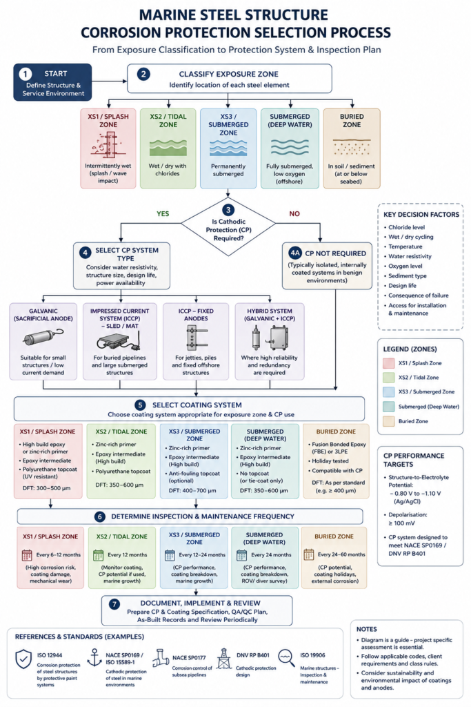
The corrosion protection strategy for any marine steel structure must be designed for the full asset life from the outset, not retrofitted piecemeal. The primary tools are:
- Protective coatings — ISO 12944 governs coating systems for atmospheric corrosion; the C5-M (marine and offshore) category specifies minimum dry film thickness and coating types for splash and tidal zones. A typical specification for a jetty pile above mean low water might require a three-coat epoxy system at 400–500 microns DFT.
- Cathodic protection (CP) — impressed current CP or sacrificial anode CP (SACP) protects steel below the waterline. Aluminium-alloy sacrificial anodes are preferred in marine environments due to their activation characteristics in chloride electrolyte; zinc anodes are better suited to freshwater or low-salinity brackish conditions. Anode consumption rates and anode spacing require design calculation per DNV-RP-B401.
- Concrete encasement — wrapping steel piles in reinforced concrete below the splash zone (composite pile construction) eliminates the metal surface from chloride exposure in the most aggressive tidal zone. This adds cost and construction programme but removes the need for CP maintenance in that zone for the design life.
- Cor-Ten and duplex stainless steels — while expensive, these materials are used in specific components (fender frames, catwalks, ladder fixings) where coating maintenance is impractical.
Reinforced concrete in marine environments presents a separate corrosion pathway: chloride ions diffuse through the cement matrix over time until they reach the reinforcement surface and exceed the threshold concentration for passive film breakdown — typically 0.4% Cl⁻ by mass of cement per BS EN 206. Once that threshold is crossed, steel corrosion begins, iron oxide expansion generates tensile stresses that crack and spall the cover, and the process accelerates rapidly. Supplementary cementitious materials (SCMs) such as GGBS (ground granulated blast furnace slag) at 50–70% replacement rates or silica fume at 7–10% are standard tools for reducing concrete permeability in XS3 exposure, reducing the chloride diffusion coefficient by a factor of 3–5 compared to plain Portland cement concrete.
Hydraulic and Wave Loading: Designing for a Moving Environment
Marine structures experience dynamic loading that has no equivalent in standard land-based structural design. Wave forces, tidal current drag, vessel berthing and mooring loads, and ship propeller wash all impose cyclic or impulsive forces on structural elements. Designing for this loading regime requires hydraulic modelling and fatigue analysis that go well beyond the static load combinations of BS EN 1990 / 1991.
Wave loading is categorised by the relationship between wave height, wavelength, and structural dimension. Where the structural element is small relative to the wavelength (the Morison equation regime), wave forces are expressed as the sum of an inertia force (proportional to water particle acceleration) and a drag force (proportional to the square of water particle velocity). The Morison equation requires drag coefficient CD and inertia coefficient CM values appropriate to the pile cross-section geometry, surface roughness, and Keulegan-Carpenter number. For larger structures — caisson walls, large-diameter monopiles — where the structure modifies the wave field, diffraction theory applies, and the Froude-Krylov approach or numerical methods are required.
Tidal currents impose sustained drag loads on piles, fender systems, and mooring hardware. For a 600mm diameter cylindrical pile in a 2.0 m/s tidal flow, the drag force per metre of pile length is approximately 1.2–1.8 kN/m depending on surface condition — modest for a single pile but significant when summed across a 40-pile jetty structure, where cumulative horizontal tidal loading can reach 500–800 kN on the deck structure. Understanding the principles of hydraulic engineering is therefore not optional background knowledge for marine structural engineers; it is a prerequisite for safe force assessment.
Vessel berthing loads represent some of the highest impulsive forces any marine structure encounters. A 50,000 DWT vessel approaching at 0.15 m/s parallel to the berth carries a kinetic energy of approximately 8–12 MJ after accounting for added mass and eccentricity. Fender systems — typically rubber cell fenders, cone fenders, or arch fenders depending on the reaction force/deflection characteristic required — absorb this energy while limiting the reaction force transmitted to the structure to a level the piles and deck can carry. Getting the fender selection wrong in either direction (under-energised fenders that allow the vessel to strike the structure, or over-stiff fenders that generate excessive pile bending) is a common and costly design error.
Geotechnical and Scour Challenges in the Marine Zone
The geotechnical challenges of marine infrastructure begin before the first pile is driven. Offshore and nearshore site investigation is logistically complex and expensive. A standard onshore borehole costs approximately £3,000–£6,000 per borehole under UK conditions; a geotechnical borehole from a jack-up barge or specialist vessel in tidal waters can cost £15,000–£40,000 per location depending on water depth, access, and soil conditions. This cost pressure leads to sparse investigation grids — and sparse investigation in variable nearshore geology leads to surprises during construction.
Soft marine clays with undrained shear strengths of 10–25 kPa are common in estuarial locations. These materials provide very low end-bearing and skin friction for driven or bored piles, pushing pile lengths to 20–35m even for moderate structural loads. Their consolidation behaviour under imposed loads — governed by their compression index Cc and coefficient of consolidation cv — means that structures built on clay-supported pile caps experience long-term differential settlement that compounds the challenges of maintaining level decks, drainage falls, and utility connections. The broader picture of geotechnical engineering challenges applies in the marine zone with additional severity, because the consequences of underestimating soft ground behaviour are harder to remediate once a structure is in service over water.
Scour protection is a distinct geotechnical discipline that draws on both hydraulics and geotechnics. The standard approach involves a filter layer of coarse granular material graded to resist movement at design flow velocities, overlain by armour rock sized per the Shields parameter and the Isbash criterion for the design current or wave condition. BS 6349-1 references appropriate scour assessment methodologies, though detailed scour design often follows specialist hydraulic model studies for significant structures. Failure to design adequate scour protection cost the UK alone hundreds of millions in premature bridge and marine structure repairs over the second half of the twentieth century — the lesson has been written into current design standards, but its application requires site-specific assessment, not formulaic compliance.
Construction Logistics and Programme Risk
Even a well-engineered marine structure can fail commercially if its construction logistics are not planned with equal rigour. Marine construction introduces constraints that have no equivalent on land: tidal windows, weather downtime, vessel availability, and the sheer cost of offshore plant mobilisation.
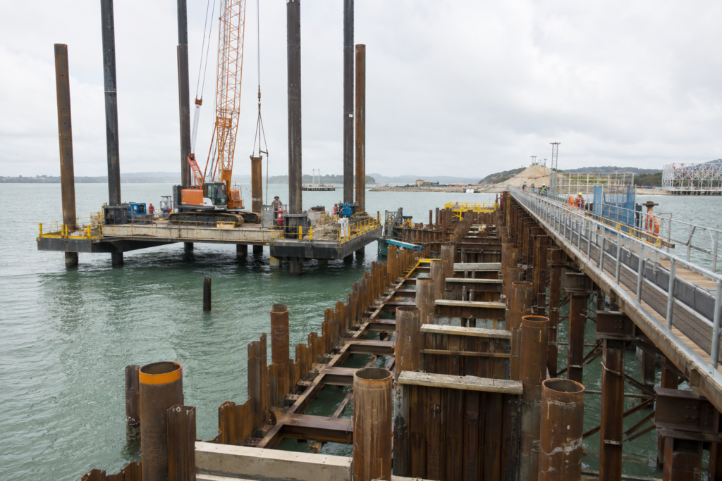
Pile driving from a floating crane barge in tidal waters is typically constrained to a 4–6 hour working window around low or high water for access and stability reasons. A contractor who expects to drive 15 tubular steel piles per week may achieve only 8–10 once tidal windows, pile handling, and splicing time are accounted for. Programme risk modelling for marine projects should treat tidal window productivity as a probabilistic variable, not a fixed assumption — a spring/neap tidal cycle that shifts the productive working window into night hours for a two-week period can cost weeks of programme.
Weather downtime is equally significant. Significant wave height limits for marine crane operations typically fall between Hs = 0.5m (for light lifts in confined berths) and Hs = 1.5–2.0m for larger offshore work barges. North Sea and West African coastal sites can experience weather downtime of 15–30% of working days in the worst seasons. Contracts that do not adequately allocate this risk between client and contractor — or that programme marine works during the most exposed season — generate disputes and claims that frequently exceed the value of the works themselves.
Temporary works in the marine environment — sheet pile cofferdams, temporary access trestles, floating plant moorings — carry risks that permanent works do not. A temporary cofferdam overtopped by a higher-than-forecast tide can flood an active excavation, lose the works, and injure workers in minutes. The challenges engineers face on water-crossing structures like bridges share many of these temporary works risks and offer useful cross-sector learning for marine project teams.
Best Practices for Managing Marine Infrastructure Challenges
The following practices reflect what separates projects that deliver on programme and within life-cycle cost from those that accumulate defects, overruns, and premature maintenance liabilities. Apply them from the feasibility stage — retrofitting these principles at detailed design is significantly more expensive.
- Commission a marine-specific ground investigation. Do not rely on interpolated borehole data from adjacent onshore investigations. Nearshore sediment sequences change rapidly over short horizontal distances. A minimum investigation density of one borehole per 25–30 metres of frontage is a reasonable starting point for a jetty or quay wall, with additional targeted holes at major pile positions.
- Define exposure zones before specifying materials. Map the structure into XS1/XS2/XS3 zones and the ALWC-risk zone (typically -0.5m to -1.0m below mean low water) before drafting the materials specification. Each zone demands a distinct protection strategy — a single generic specification applied across the whole structure either over-specifies in low-risk zones or under-specifies in the critical ones.
- Model scour as a design load, not an afterthought. Scour reduces effective pile length, alters pile head fixity assumptions, and changes the load distribution across a pile group. It should appear as a defined load case in the structural analysis model, with scour depth verified by a hydraulic engineer using site-measured current and wave data.
- Design the inspection and maintenance regime at the same time as the structure. Access provisions for underwater inspection — fixed inspection platforms, diving ladder positions, ROV launch points — cost very little when designed in. They cost enormously when retrofit to an operational structure over water.
- Require CP monitoring from day one. Install potential monitoring reference electrodes during construction. Half-cell potential surveys on a two-to-three-year cycle confirm that the CP system is maintaining steel potentials within the protective range per BS EN 13174 (−0.80V to −1.10V vs Ag/AgCl/seawater reference). A CP system that has drifted outside this range for two or three years will have lost years of protection life — and you will not know without monitoring.
- Engage a marine specialist at RIBA Stage 1 (or equivalent). The decisions made at feasibility and concept design — structure type, pile system, foundation concept, exposure management strategy — lock in 70–80% of the life-cycle cost of a marine structure. Bringing in specialist marine engineering input at concept stage, rather than at detailed design, is the single highest-value intervention available to a project client.
- Plan construction sequences around tidal and weather data, not calendar assumptions. Use hindcast metocean data from the project site to establish realistic weather window probabilities for each phase of marine works. The Meteorological Office, CEFAS, and commercial metocean data providers maintain long-record datasets for UK and international sites that allow proper probabilistic programme modelling.
Across all of these practices, the common thread is that marine infrastructure rewards thorough front-end investment — in investigation, modelling, specification, and planning — and penalises shortcuts with disproportionate cost and schedule consequences. The broader marine infrastructure guide on this site sets out how these principles apply across different structure types and project scales.
Frequently Asked Questions About Marine Infrastructure
These questions reflect what engineers, project managers, and owners commonly ask when working on marine infrastructure for the first time or facing unfamiliar site conditions.
Q: What are the main causes of failure in marine infrastructure?
A: The primary causes are corrosion of structural steel (particularly ALWC in the tidal zone), chloride-initiated reinforcement corrosion in concrete, scour of foundation elements, and fatigue under cyclic wave and vessel berthing loads. In the majority of documented marine structure failures, more than one mechanism acted concurrently — for example, a pile weakened by ALWC section loss then fails under a wave loading event that its reduced section can no longer carry. Early detection through systematic inspection under schemes like the Ports and Harbours Inspections Protocol (PHIP) in the UK is the most effective mitigation.
Q: What standards govern marine infrastructure design in the UK?
A: The primary UK reference series is BS 6349 (Maritime Structures), which covers general criteria (Part 1), design of quay walls (Part 2), jetties (Part 3), fendering (Part 4), moorings (Part 5), and floating structures (Part 6). BS EN 1997-1 (Eurocode 7) governs geotechnical design for foundations and retaining walls. Concrete and steel structural design follows BS EN 1992 and BS EN 1993 respectively, with marine exposure classes defined in BS EN 206. Corrosion protection for coating systems references ISO 12944; cathodic protection design references DNV-RP-B401 and BS EN 13174.
Q: How much does marine infrastructure typically cost compared to equivalent land-based construction?
A: Marine construction carries a cost premium of 40–120% over equivalent land-based works, depending on water depth, tidal range, wave exposure, and distance from quayside infrastructure. A simple access jetty in a sheltered harbour might be constructed at £8,000–£15,000 per linear metre. A fully equipped port berth capable of handling vessels of 30,000–50,000 DWT can cost £25,000–£60,000 per metre of berth length at 2024 UK prices, exclusive of dredging, reclamation, and landside civil works. Offshore structures in exposed locations command further premiums driven by weather downtime, vessel day rates (£30,000–£120,000/day for heavy lift barges), and extended pile lengths in deep or soft ground.
Q: What is the difference between a jetty and a quay wall in marine infrastructure?
A: A quay wall is a continuous retaining structure built along a waterfront, typically of mass concrete, reinforced concrete, or steel sheet pile construction, which retains fill behind it and provides a berthing face at the front. A jetty is an open-piled structure that extends out from the shoreline, supported on piles driven into the seabed with open water beneath the deck — it does not retain fill. Jetties offer advantages in soft ground or high tidal range locations where a continuous wall would require expensive deep foundations; quay walls provide more flexible landside access and can accommodate heavy vehicle and crane loads more readily due to their solid deck on fill.
Q: How is scour protection designed for marine structures?
A: Scour protection design starts with a hydraulic assessment of the current velocities and wave orbital velocities at the seabed around the structure under design storm conditions. The required armour stone size is calculated using the Isbash criterion or the van Rijn approach for current-dominated conditions, or the Hudson formula equivalent for wave-dominated conditions. A filter layer is placed first — granular material graded so that d85 of the filter is less than d15 of the armour — to prevent seabed migration through the armour layer. Typical armour stone for a jetty pile in a 2.0–3.0 m/s current environment weighs 200–1,000 kg per stone, with the protection layer extending at least 3–5 pile diameters from the pile centreline.
Navigating Marine Infrastructure Challenges Requires Specialist Input
Marine infrastructure challenges do not yield to generic engineering approaches. The convergence of aggressive corrosion environments, complex geotechnical conditions, dynamic hydraulic loading, and costly construction logistics means that every significant marine project requires engineers who understand how these factors interact — and how to sequence design decisions so that solutions in one area do not create problems in another. Specifying high-durability concrete without modelling the scour condition that will expose the pile shaft below the mud line is half an answer. Designing an efficient pile foundation without planning the inspection access to maintain it is creating a future liability.
StruviaCore brings specialist structural and civil engineering expertise to marine projects across the full asset lifecycle — from feasibility site assessment and marine geotechnical interpretation through to detailed structural design, corrosion protection specification, and construction oversight. If you are planning a port facility, coastal structure, or river infrastructure project and need engineering input that understands the marine environment from first principles, explore what StruviaCore’s marine infrastructure services cover or contact us directly to discuss your project requirements.
Leave a Reply