
Drive over a potholed urban road after the first rains, and you quickly realise that a road is not simply tarmac poured on dirt. Roads are layered structural systems — engineered to transfer wheel loads through successive strata of bound and unbound materials down to the natural subgrade below. Get any layer wrong, and the road fails: rutting, cracking, subsidence, or outright collapse.
Yet roads remain one of the least understood categories of civil infrastructure. Engineers working on buildings or bridges often treat road construction as the simpler discipline. It rarely is. A road must perform under dynamic loading, temperature cycling, waterlogging, and decades of accumulated fatigue — all while being maintained with live traffic running overhead. Understanding how roads work at a structural and material level is the foundation of any competent road design, supervision, or maintenance regime. This article breaks down the full process: from soil investigation and layer design through to construction sequencing, quality assurance, and the most common failure modes engineers face on site.
Roads work by distributing traffic wheel loads through a layered pavement structure — typically subbase, base course, and wearing course — each designed to reduce stress before it reaches the subgrade soil. The subgrade’s California Bearing Ratio (CBR) determines the total pavement thickness required to prevent structural failure under design traffic loading.

What a Road Actually Is: The Layered Pavement System
Road construction is the discipline of designing, building, and maintaining a pavement structure that safely transfers traffic loads to the underlying ground without exceeding the deformation or stress limits of any individual layer. The road is not a monolithic slab — it is a carefully sequenced assembly of materials, each serving a distinct structural and drainage function.
The fundamental concept driving road design is load spread. A single axle on a heavy goods vehicle can exert 80–100 kN on the road surface. Without a pavement structure, that load would be concentrated on a very small contact area, producing pressures of 500–700 kPa at the tyre — far in excess of what most natural soils can carry without plastic deformation. The pavement layers progressively spread that load, so that by the time the stress reaches the subgrade, it has reduced to 20–50 kPa or less, within the subgrade’s bearing capacity.
The Standard Layer Sequence
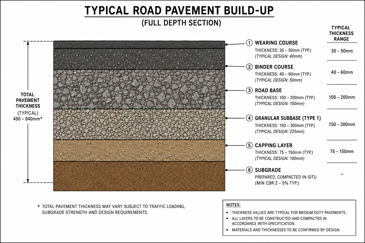
Working from the bottom up, a typical flexible pavement cross-section comprises:
- Subgrade: The natural or engineered soil on which the entire pavement structure sits. Its strength, measured by the California Bearing Ratio (CBR), determines how thick the overlying construction must be. A poor clay subgrade with a CBR of 2–3% demands far more depth than a granular subgrade at CBR 15%.
- Capping layer: Used when the subgrade CBR falls below 5% — typically a 150–350mm layer of imported granular fill or stabilised material that effectively improves the platform the pavement is built from. This layer is frequently omitted on design drawings and regretted on site.
- Granular subbase: A compacted granular layer, commonly Type 1 unbound crushed aggregate conforming to the Specification for Highway Works (SHW) Clause 803, ranging from 150mm to 300mm thick depending on design traffic. It provides a working platform and contributes to load spread.
- Road base (base course): The primary structural layer, either unbound aggregate (Dense Bitumen Macadam or Dry Bound Macadam in older specs) or hydraulically bound material. This is the layer that does the most structural work in distributing loads laterally.
- Binder course: An intermediate bituminous layer between the road base and the wearing surface, typically 60–80mm thick. It provides a degree of waterproofing and bonds the wearing course to the base.
- Wearing course: The finished running surface, typically 40–50mm of hot rolled asphalt, stone mastic asphalt, or high stone content surface course. It resists traffic wear, provides skid resistance, and sheds surface water. Mix design and aggregate selection here directly affect road safety.
For rigid pavements — concrete roads — the upper layers are replaced by a reinforced or unreinforced concrete slab, typically 200–300mm thick, with a granular sub-base below and expansion/contraction joints at regular intervals (typically 5–6m for jointed reinforced concrete, or continuous reinforcement over longer runs). Rigid pavements have a higher initial cost but substantially lower long-term maintenance requirements, which is why they remain preferred for heavily trafficked industrial roads, port aprons, and airfields.
Flexible vs. Rigid: Which Pavement Type to Use
The choice between flexible and rigid construction is rarely straightforward. Flexible pavements deform slightly under load and recover — a visco-elastic response that accommodates differential settlement better than rigid construction. They are faster to repair but fatigue over time, accumulating permanent deformation that eventually requires resurfacing or reconstruction. Rigid pavements are stiffer, distribute loads over a wider area, and resist rutting — but crack under differential settlement, and repairs demand specialist equipment and extended traffic management windows.
In practice, the choice depends on subgrade conditions, traffic volume and composition, available materials, maintenance budget, and construction programme. A lightly trafficked residential street in a low-lying, high-water-table setting might suit flexible construction with an improved drainage regime. A container terminal road carrying 60-tonne straddle carriers will almost always be rigid or composite construction. Our detailed roads guide covers the selection criteria in full, including life-cycle cost comparisons between the two pavement families.
How Road Design Works: Traffic Loading and Pavement Thickness
Pavement thickness design is not guesswork — it is a quantified process driven by two principal inputs: the strength of the subgrade and the cumulative traffic loading the road must carry over its design life. In the UK and most countries following British standards, the standard method for flexible pavement design is set out in HD 26/06 (Design Manual for Roads and Bridges, Volume 7) and the Highways England Interim Advice Note IAN 73/16. Similar frameworks exist in most jurisdictions, though the specific documents vary.
Traffic loading is expressed in terms of Equivalent Standard Axles (ESAs) — a normalisation technique that converts mixed traffic (cars, buses, lorries) into equivalent passes of a single 80 kN standard axle. A single 10-tonne axle causes approximately the same pavement damage as 1 ESA. A 20-tonne axle causes approximately 16 times more damage due to the fourth-power relationship between axle load and pavement fatigue — a figure known as the Equivalent Axle Load factor. This is why overloaded lorries destroy roads disproportionately: doubling the axle load increases pavement damage by a factor of 16, not 2.
Design traffic is typically expressed as the cumulative number of ESAs over a 20–40 year design life. A lightly trafficked road might see 0.5 million ESAs (msa). A national highway in a high-growth economy could see 30–80 msa. The subgrade CBR and design ESA value together determine which pavement thickness chart or design catalogue to use.
Subgrade Investigation and CBR Testing
Before any pavement design can proceed, the subgrade must be characterised. This typically involves a combination of trial pits, dynamic cone penetrometer (DCP) testing, and laboratory CBR tests on remoulded samples at the design moisture content. For major road schemes, plate loading tests and FWD (Falling Weight Deflectometer) testing of existing pavement may supplement laboratory work.
The moisture condition at which the CBR is determined matters enormously. A clay subgrade may test at CBR 8% in a dry summer and drop to CBR 2% after prolonged wet weather. Design must use the equilibrium moisture condition — the long-term in-service moisture content — not the as-tested value. Failing to account for seasonal moisture variation is one of the most consistent errors in low-volume road design on expansive clay soils.
In regions with tropical or lateritic soils — common in West Africa, for instance — the standard UK-derived CBR correlations can be unreliable. Local calibration and experience are necessary. The geotechnical investigation programme should be proportionate to the road’s traffic loading and the variability of site conditions. For a comprehensive treatment of subgrade investigation methods, our introduction to pavement engineering sets out the testing sequence from desktop study through to design recommendations.
Road Construction Sequencing: What Happens on Site
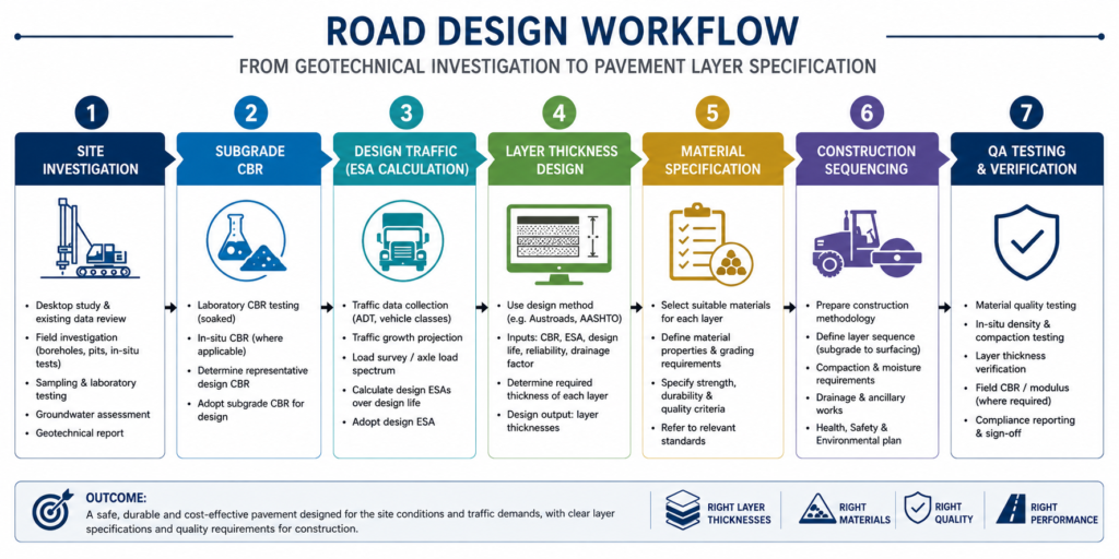
Understanding how roads work is inseparable from understanding how they are built. The construction sequence is as important as the design — compact a layer at the wrong moisture content, fail to achieve density, or place material in excessively thick lifts, and the pavement will underperform regardless of how well it was designed on paper.
The construction sequence for a new flexible road typically proceeds as follows:
- Earthworks and formation preparation: The existing ground is stripped of topsoil and vegetation to the formation level — the top of the subgrade on which the pavement structure sits. The formation is proof-rolled with a loaded articulated lorry (minimum 20 tonnes GVW) to detect soft spots, and any areas of failure are cut out, treated, or replaced before the pavement build-up begins. Proof rolling is a contractual requirement on most UK highway contracts and is specified under the SHW Clause 618.
- Drainage installation: Edge drains, filter drains, and carriageway drainage connections are installed before subbase placement. Drainage is not an afterthought — water in the subgrade is the primary cause of long-term pavement deterioration, and a well-drained road will outlast an identical road with poor drainage by a factor of two or more.
- Subbase and capping placement: Granular materials are placed in compacted layers not exceeding 200–225mm each, with compaction plant and number of passes specified per material type. In-situ density testing (sand replacement, nuclear density gauge, or PANDA probe) confirms that the specified relative compaction — typically 95% of maximum dry density per BS 1377 — has been achieved before the next layer is placed.
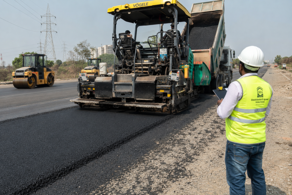
- Bituminous base and binder course laying: Asphalt materials are delivered from a licensed mixing plant and laid using a self-propelled paver. Temperature at delivery and at the point of laying is critical — most hot mix asphalts must be laid above 120°C and compacted before the mat drops below 80°C. Cores taken from the finished surface confirm layer thickness and air void content, with a maximum of 6% voids in the wearing course per BS EN 13108-1.
- Wearing course and surfacing: The final surface is laid, and skid resistance is tested using the Pendulum Test or, on strategic road network schemes, the SCRIM machine (Sideways-force Coefficient Routine Investigation Machine). The design skid resistance value varies by road category and geometry — sharper bends and approach zones to junctions require higher values per HD 36/06.
Throughout construction, the contractor’s quality management system and the engineer’s independent inspection regime run in parallel. For public roads, this typically means a Contractor’s Quality Plan against the SHW, with independent testing at agreed frequencies. The most common challenges in road construction — including earthworks over soft ground, drainage failures, and asphalt temperature management — each require a specific contractual and technical response.
Common Failure Modes and What Causes Them
Roads fail in predictable ways. Knowing the failure mode tells you where in the pavement structure the problem lies — and whether it can be remediated at the surface or requires reconstruction. This is not academic: incorrect diagnosis leads to wasted maintenance spend and premature failure of the repair itself.
The principal failure modes engineers encounter are:
- Rutting: Permanent deformation in the wheel tracks. Shallow rutting (less than 10mm) is typically a wearing course failure — plastic deformation in the asphalt mix due to high temperatures, excessive bitumen content, or the use of rounded aggregates. Deep rutting (greater than 20mm) indicates structural failure in the base or subgrade. Surface-only treatment of deep rutting will fail within one to two wet seasons.
- Alligator (fatigue) cracking: A network of interconnected cracks across the wheel path. This is the classic signature of pavement fatigue — the base course has exceeded its fatigue life from repeated load applications. Water infiltration through cracks accelerates subgrade softening, compounding the failure rapidly. Repair requires removal and replacement of the full pavement structure in affected areas, not just surface crack sealing.
- Longitudinal cracking: Cracks running parallel to the road centreline. When they appear in the wheel tracks, they often indicate base course delamination or horizontal shear at a layer interface. When they appear at the road edge, they typically indicate inadequate edge support — a drainage failure, eroded verge, or inadequate haunch thickness.
- Potholing: Discrete holes in the road surface, typically the end stage of fatigue cracking combined with surface water infiltration and freeze-thaw cycling. Potholes form rapidly once water penetrates the wearing course and saturates the base. Patching of individual potholes is a temporary measure; recurrence indicates a structural problem requiring investigation.
- Settlement and depression: Longitudinal or transverse depressions in the road surface indicate movement in the subgrade or embankment fill below. The cause may be consolidation of soft ground, collapse of buried services, or failure of an embankment slope. Unlike bituminous layer failures, subgrade settlements cannot be remedied by surface treatments.
The design life of a road pavement — typically 20–40 years for a principal road — is a fatigue life, not an absolute durability. The pavement is designed to absorb a specific number of ESAs before requiring major structural intervention. Maintenance overlays and surface treatments extend the surface life without resetting the structural clock; only reconstruction addresses the accumulated fatigue in the structural layers.
Best Practices for Road Construction and Maintenance
Decades of highway engineering research and project post-mortems have produced a clear set of practices that separate roads that last from those that fail prematurely. The following checklist applies to engineers involved at any stage — from design brief through to post-construction inspection. You should treat these not as aspirations but as minimum standards of professional practice.
- Conduct ground investigation before design, not after. Pavement design based on assumed CBR values rather than tested subgrade data is a recurring cause of structural failure. Commission a site-specific geotechnical investigation commensurate with the road category and length. A saving of £5,000 on investigation costs can result in a £500,000 reconstruction bill.
- Design the drainage before the pavement. The pavement thickness design assumes a drained subgrade. If the drainage system cannot maintain the assumed equilibrium moisture content, the design CBR will not be achieved in service. Install edge drains, French drains, and cross-drainage culverts as the first construction activity, not the last.
- Specify and enforce compaction standards layer by layer. Specifying density targets in the contract documents is not enough — verify each layer before the next is placed. Remediation of compaction failures after subsequent layers have been laid is time-consuming, disruptive, and often inadequate.
- Manage asphalt temperature rigorously. Cold asphalt cannot be properly compacted. Verify delivery temperatures at the mixing plant and at the point of laying. Reject loads that have dropped below the minimum laying temperature. Cold joints and poorly compacted patches are primary sites for water infiltration and premature failure.
- Document as-built thicknesses and material test results. Core holes taken at handover confirm layer thicknesses match the design intent. Without this data, future maintenance engineers have no reliable baseline. Maintain a road asset register that captures construction records, material properties, and subsequent maintenance interventions.
- Carry out regular condition surveys. Periodic visual condition surveys and deflectograph or FWD deflection measurements allow early identification of structural deterioration, enabling timely surface treatment before the road reaches a condition requiring full reconstruction. The cost ratio between surface treatment and full reconstruction is typically 1:6 to 1:10.
- Control construction traffic during the works. Heavy construction plant running over newly placed subbase or soft formation causes more early-life pavement damage than years of normal traffic. Impose haul road routes and weight restrictions during the earthworks phase, and specify the minimum pavement thickness to be in place before heavy construction vehicles can use the formation as a running surface.
For a structured approach to highway scheme delivery from initial feasibility through to maintenance regime, our pavement engineering guide covers mix design, structural analysis, and maintenance planning in detail. Road engineers working on transport schemes involving multiple infrastructure modes should also cross-reference the transportation engineering guide for context on junction design, road hierarchy, and traffic modelling.
Frequently Asked Questions About Roads
Q: What is the difference between flexible and rigid road pavement?
A: A flexible pavement uses bituminous (asphalt) layers over a granular base and deforms slightly under load, distributing stress through the material’s visco-elastic properties. A rigid pavement uses a concrete slab that spans between supports and distributes load over a wider area through the slab’s bending stiffness. Flexible pavements are more common due to lower initial cost and easier patching, but rigid pavements offer longer structural life under heavy loading with lower long-term maintenance requirements.
Q: How thick does a road need to be?
A: Total pavement thickness depends on subgrade CBR and design traffic loading. For a lightly trafficked estate road on a subgrade with CBR 5%, a total pavement depth of 450–550mm (including subbase) is typical. A heavily trafficked primary distributor road carrying 30 million standard axles over its design life may require 750–900mm total construction depth. These figures are derived from the HD 26/06 design catalogue, and site-specific investigation is required before any thickness is confirmed.
Q: What causes potholes in roads?
A: Potholes result from water penetrating through cracks or failed seals in the wearing course and saturating the layers below, reducing their load-bearing capacity. Freeze-thaw cycles expand trapped water and accelerate the process. The initial crack may form through fatigue, thermal movement, or poor construction joints. Potholes are a symptom of structural deterioration, not a standalone surface defect — patching without addressing the underlying drainage or structural cause leads to rapid reappearance.
Q: What is a CBR test and why does it matter for road design?
A: The California Bearing Ratio (CBR) is a measure of the shear strength of a soil relative to a standard crushed stone, expressed as a percentage. A CBR of 100% represents the standard material; natural subgrades typically range from 2% (soft clay) to 20% (dense gravel). The CBR is the primary input to flexible pavement thickness design — a low CBR subgrade requires a thicker pavement to spread wheel loads before they reach the ground. CBR testing is carried out per BS 1377: Part 4 using either laboratory or in-situ test methods.
Q: How long does a road last before it needs resurfacing?
A: A well-designed and maintained bituminous wearing course has a service life of 12–20 years on a principal road, depending on traffic intensity, climate, and drainage conditions. The structural pavement beneath it is designed for 20–40 years before major reconstruction. Maintenance overlays — typically 40–50mm of new wearing course — can extend the surface life without addressing the structural layers, but this approach is only valid while the underlying base remains sound. Deflection testing confirms whether the structure can support a surface treatment or requires deeper intervention.
Roads work because every layer in the pavement system does a specific job. The subgrade carries the final load; the subbase provides a working platform and contributes to load spread; the base absorbs the structural fatigue; the wearing course resists traffic and sheds water. Remove or compromise any one of these elements, and the system fails — not dramatically, but gradually, through the accumulated damage of thousands of load cycles that the weakened structure cannot sustain.
Getting road construction right starts at the ground investigation stage, not the asphalt paver. It demands rigorous compaction control, properly sequenced drainage, and consistent quality assurance from formation to finished surface. The roads that fail prematurely almost always trace that failure back to a decision made early — a CBR assumed rather than tested, a drainage detail omitted to save programme time, or a cold asphalt mat that was compacted anyway.
If you are working on a road scheme — whether a new carriageway, a rehabilitation project, or a development access road — and need independent technical input on pavement design, ground investigation, or construction supervision, contact the StruviaCore team. Our civil and structural engineers bring practical site experience to every stage of the road design and delivery process.
Leave a Reply