

Walk through any major city — Lagos, London, or Los Angeles — and you are standing on a layered stack of engineered systems that most people never think about until something fails. A burst water main floods a junction. A potholed arterial road backs up freight movement for kilometres. A bridge closure forces thousands of commuters onto already-stressed alternative routes. These are not abstract risks. They are the daily consequence of urban infrastructure that was either poorly designed, poorly maintained, or simply overwhelmed by growth it was never sized for.
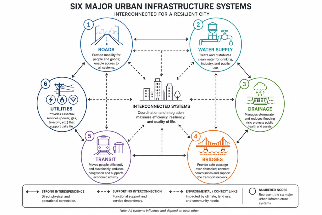
Urban infrastructure is the collective term for the physical systems that support city life: roads, bridges, water supply and drainage networks, stormwater management, public transit, power distribution, and waste management. Each system is a civil engineering discipline in its own right, and each interacts with the others in ways that make integrated planning — not piecemeal intervention — the only sensible approach. This article walks through the most common urban infrastructure examples, explains how each is engineered, and identifies where failures typically originate.
Urban Infrastructure Examples: Quick Answer
Urban infrastructure examples include road networks, drainage and stormwater systems, water supply pipelines, bridges and overpasses, public transit corridors, and utility distribution networks. Each system is designed to a set of national or international standards, sized for projected demand, and maintained over a defined service life to keep a city functional.
What Urban Infrastructure Actually Covers
The term gets used loosely in policy documents and procurement briefs, so it is worth being precise. Urban infrastructure divides into two broad categories: grey infrastructure, which refers to the conventional engineered systems built from concrete, steel, asphalt, and pipework; and green infrastructure, which incorporates natural or semi-natural systems — detention ponds, bioswales, urban tree canopies — to manage stormwater, urban heat, and air quality alongside conventional systems.
Most cities run on a combination of both, though the balance has shifted as climate adaptation has moved from aspiration to procurement requirement. Understanding that distinction matters because it affects design standards, maintenance regimes, and the skills a project team needs. A road drainage system that incorporates roadside bioswales, for example, requires input from a geotechnical engineer, a hydraulic engineer, and a landscape architect — not just a highways designer.
The Six Core Urban Infrastructure Systems
For the purposes of structural and civil engineering practice, the following six systems constitute the backbone of urban infrastructure:
- Road networks — carriageways, footways, junctions, and associated signage and drainage
- Bridge and overpass structures — spanning roads, railways, watercourses, and valleys
- Water supply and distribution — from treatment works to the point of connection at individual buildings
- Stormwater and surface water drainage — including culverts, attenuation tanks, and outfalls
- Foul and combined sewerage — collection, conveyance, and treatment
- Public transit infrastructure — bus rapid transit (BRT) corridors, rail stations, park-and-ride facilities, and associated civil works
Power distribution and telecommunications are typically designed by electrical and mechanical engineers, though civil engineers provide the buried duct networks, substations, and access chambers that those systems rely on. The boundary between disciplines is not always clean on site, and that ambiguity is one of the more common sources of coordination failure on complex urban projects.
For further context on how these systems are planned and governed at the project level, the urban infrastructure guide on this site covers procurement frameworks and delivery models in more depth.
Road Networks: Design, Standards, and What Goes Wrong
Roads are the most visible urban infrastructure example and, statistically, the most failure-prone. The failure modes are well understood: inadequate pavement design for actual traffic loading, insufficient drainage causing premature deterioration, poorly compacted subgrade, and maintenance cycles that do not match the rate of degradation. Getting the design right from the start is cheaper by an order of magnitude than reactive repair.
Pavement Design and Structural Layers
A road pavement is a layered structure. From the surface down, a typical flexible pavement in a UK-adopted context includes: a wearing course (typically 40mm of dense bitumen macadam or stone mastic asphalt), a binder course, a base layer of asphalt or crushed aggregate, a sub-base of granular material (often Type 1 crushed rock to a minimum depth determined by design CBR), and the prepared subgrade. The Highways England (now National Highways) design method, published in the Design Manual for Roads and Bridges (DMRB), specifies thickness requirements based on cumulative traffic loading expressed in standard axles (ESAs).
Where subgrade conditions are weak — as they frequently are in areas underlain by expansive clays or seasonally high water tables — a geotechnical investigation is required before any pavement design can proceed. California Bearing Ratio (CBR) values from trial pits or in-situ tests feed directly into the pavement thickness calculation. Skipping this step and relying on assumed values is one of the most consistent causes of early pavement failure on urban road projects.
Rigid pavements — reinforced or unreinforced concrete — are used where heavy or channelised loads are expected, such as bus layovers, container yards, and heavily trafficked junctions. They have a longer service life than flexible pavements but are more expensive to repair when they do fail. Joint design is critical: poorly spaced or poorly sealed expansion and contraction joints allow water ingress, which rapidly accelerates deterioration of the subbase.
Drainage: The Most Neglected Road Component
Road drainage is frequently under-designed and, once built, under-maintained. Surface water that cannot be discharged off the carriageway quickly saturates the pavement structure, reduces bearing capacity, and accelerates rutting. The hydraulic design of gullies, kerb drainage channels, filter drains, and outfalls must be sized for a storm event appropriate to the road’s importance and design life — typically the 1-in-30-year event for minor roads and the 1-in-100-year event for major carriageways, with freeboard for climate change uplift as required by local planning policy.
In many urban contexts, discharge to a formal sewer or watercourse is restricted. SuDS (Sustainable Drainage Systems) requirements now apply to most new road drainage in England and Wales under Schedule 3 of the Flood and Water Management Act 2010 (as commenced). This means attenuation, infiltration, or treatment measures must be incorporated at source — not simply routed to an existing pipe that is already at or near capacity.
Explore the technical principles behind hydraulic sizing in our article on hydraulic engineering examples, which covers flow calculations and culvert design in detail.

Bridges and Overpass Structures in Urban Environments
Urban bridges are structurally demanding in ways that rural bridges are not. They carry higher traffic volumes with a more complex mix of loading — HGVs, buses, cyclists, and pedestrians often share the same structure. They sit in constrained corridors where access for inspection and maintenance is difficult. And they are subject to more aggressive environments: de-icing salt, vehicle exhaust, and the thermal cycling that comes with being surrounded by hard urban surfaces.
The structural form selected for an urban bridge depends on the span, the clearance requirements beneath, the available construction depth, and the programme constraints. Beam bridges — using precast prestressed concrete (PPC) beams or steel plate girders — are the most common form for spans between 10m and 40m. They are fast to construct and well-understood, but they require relatively deep construction depth, which can be a constraint in undercrofts where headroom is tight.
Integral bridges, where the deck is connected rigidly to the abutments without expansion joints, have become the preferred form for bridges up to approximately 60m total length in the UK following guidance in the DMRB (BD 57/01 and its successors). Eliminating joints removes the most common maintenance failure point — leaking joints that allow chloride-laden water to attack substructure elements. The trade-off is more complex structural behaviour under temperature and traffic loading, requiring careful finite element analysis.
For urban footbridges, dynamic behaviour governs the design in ways that static loading does not. A footbridge with a natural frequency close to the walking pace of a crowd (approximately 2Hz) will experience resonance — the Millennium Bridge in London being the most widely cited example, though it was corrected promptly after opening. Current design guidance, including the UK National Annex to BS EN 1991-2, requires pedestrian-induced dynamic analysis for all footbridges where crowd loading is anticipated.
Our article on bridges expands on structural forms, material selection, and inspection regimes for bridge assets across their full service life.
Water Supply and Drainage: The Infrastructure Nobody Sees
Buried utility infrastructure — water mains, foul sewers, surface water sewers, and combined sewers — constitutes a significant proportion of a city’s total infrastructure asset value, yet it is the least visible and the least consistently maintained. Cities in many parts of the world operate on pipe networks that are 80 to 100 years old, designed for population densities that no longer reflect reality.
Water supply networks are designed around two primary criteria: pressure and flow. Residual pressure at the point of delivery must typically be maintained above a minimum (35 metres head in many UK water company standards), and peak daily demand — factoring in population density, commercial and industrial use, and fire-fighting reserve — must be met without drawing the network below that threshold. Where pressure varies significantly across a distribution zone, pressure management zones (PRZs) with pressure-reducing valves (PRVs) are used to prevent pipe failures in low-lying areas and reduce non-revenue water loss from leakage.
Sewer design involves a different set of calculations. A gravity foul sewer must be designed to flow at no more than 75% capacity under peak flow conditions (maintaining a self-cleansing velocity of at least 0.75 m/s to prevent sediment deposition), with sufficient gradient to achieve this without requiring pumping wherever possible. In flat urban terrain, this is not always achievable, and pumping stations become a necessary element of the drainage strategy — with all the operational and maintenance implications that brings.
The interaction between water supply infrastructure and geotechnical conditions deserves particular attention. Poorly backfilled pipe trenches are a known source of differential settlement in overlying road pavements. In expansive clay soils — common across parts of London, the Midlands, and many tropical urban environments — seasonal moisture changes cause heave and shrinkage that can fracture buried mains. Specifying polyethylene (PE) or ductile iron pipe with restrained joints in high-risk ground conditions is a relatively low-cost design decision that avoids expensive reactive repair.
The engineering of stormwater and drainage systems connects directly to geotechnical considerations — a connection explored in our piece on geotechnical engineering.
Urban Transit Infrastructure: Corridors, Stations, and Civil Works
Public transit infrastructure sits at the intersection of civil, structural, and geotechnical engineering. A bus rapid transit (BRT) corridor requires dedicated carriageway design, typically a reinforced concrete or thick asphalt surface capable of handling the channelised loading of 18-tonne buses at high frequency. Station platforms, shelters, lighting columns, and information systems require structural design. Underpasses and at-grade crossings require traffic engineering input.
Light rail and metro systems add tunnel structures, cut-and-cover boxes, elevated viaducts, and deep station excavations to the mix. The geotechnical risk on any underground transit project is substantial. Tunnelling through mixed ground — the kind of geology found beneath most large cities where alluvial deposits overlie variable rock — requires careful geotechnical investigation, ground treatment, and monitoring. Settlement of the surface above a tunnel can damage existing buildings and services; the acceptable settlement limits are typically defined in millimetres and are tightly controlled during construction.
Park-and-ride facilities and interchange structures are often overlooked as civil engineering projects, but they involve multi-storey car parks (structural design of post-tensioned flat slabs or precast frame systems), retaining walls, drainage, access road design, and sometimes bridge structures connecting to rail platforms. The full scope of civil works on a transit project is rarely reflected in the headline costs quoted in public announcements.
For a broader view of how transit infrastructure connects to urban mobility planning, our article on urban mobility covers the policy and engineering interface in city transport planning.
Common Challenges in Urban Infrastructure Projects
Urban infrastructure projects fail — financially, technically, or both — for a predictable set of reasons. Identifying them early is the single most effective form of risk management available to a project team.
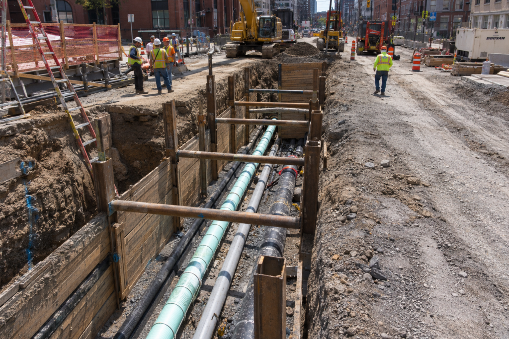
Utility conflicts are the most consistent source of programme overrun on urban civil works. Buried utilities — some unmapped, some mapped inaccurately — are struck during excavation, triggering service diversions that were not in the original programme or budget. A pre-construction utilities survey using ground-penetrating radar (GPR), combined with a utility mapping exercise that cross-references all available records, reduces this risk materially. It does not eliminate it. Any programme for urban excavation should carry a contingency allowance for utility conflicts.
Ground conditions that differ from those assumed in design cause more construction claims than almost any other single factor. An urban site may have been built on, demolished, and built on again multiple times. Made ground — fill of variable quality including demolition rubble, ash, and sometimes contaminated material — is common beneath urban surfaces and behaves unpredictably under load. A geotechnical desk study, followed by a Phase 1 and where necessary Phase 2 ground investigation, is not optional. It is the baseline of defensible design.
Traffic management and access constraints in urban environments compress working hours, restrict plant sizes, restrict spoil removal, and add cost. A rural bridge that might be constructed in eight months takes 18 months in a city centre because the site is only accessible at night, the road cannot be closed during the day, and deliveries must be booked to avoid peak-hour conflicts. These realities must be built into the project programme and cost plan from the start, not discovered during tender.
Stakeholder management — particularly with utility companies, local authorities, and adjacent landowners — extends planning and consenting programmes significantly. On major urban infrastructure projects, the pre-construction phase often takes longer than the construction phase itself. Project managers who treat stakeholder engagement as an administrative task rather than a technical risk tend to find out why this matters the hard way.
Understanding cost drivers in urban infrastructure links directly to structural engineering cost factors — a subject covered in depth in our structural engineering cost factors guide.
Best Practices for Urban Infrastructure Delivery
There is no single formula for delivering urban infrastructure well, but there are disciplines that consistently distinguish projects that succeed from those that do not. The following practices apply across road, drainage, bridge, and transit projects.
Front-load your ground investigation. The cost of a thorough geotechnical investigation — trial pits, boreholes, in-situ tests, laboratory analysis — is typically between 0.1% and 0.5% of the project value. The cost of ground-related surprises during construction routinely runs to 5–15% of the contract sum. The arithmetic is not complicated.
Design for buildability, not just compliance. A design that meets all relevant codes but cannot be physically built within the site constraints is not a good design. Involve contractors early in the design process — particularly on complex urban sites — to identify sequence issues, access constraints, and plant limitations before they become problems on site.
Verify your drainage strategy against climate change allowances. Current UK planning policy requires drainage designs to account for a 40% increase in peak rainfall intensity over the design life of the infrastructure. Many existing drainage systems were designed without this allowance and are already operating at or beyond capacity. New works must not make this worse, and the drainage strategy must demonstrate, not assume, that it will not.
Use BIM as a coordination tool, not a documentation exercise. A federated BIM model that combines structural, civil, mechanical, and electrical models in a common data environment allows clash detection before construction, not during it. On a project with a complex utility environment, this can identify hundreds of potential conflicts that would otherwise emerge during excavation. The BIM guide on this site covers implementation in more detail.
Set up a monitoring regime before construction starts. Settlement monitoring points on adjacent buildings, groundwater monitoring wells, and vibration monitoring near sensitive structures give you a baseline against which construction effects can be measured. Without a pre-construction baseline, it is impossible to demonstrate — or defend — what your works did or did not cause.
Write a clear O&M manual and hand it over. Infrastructure that is not maintained fails. A well-written operations and maintenance manual, handed over at practical completion, is not a formality. It is the document that determines whether the asset you designed survives to the end of its intended service life or deteriorates in a decade through neglect.
Frequently Asked Questions About Urban Infrastructure
Q: What is urban infrastructure in civil engineering?
A: Urban infrastructure in civil engineering refers to the physical systems that allow a city to function: roads, bridges, water supply and sewerage networks, stormwater drainage, public transit structures, and utility distribution networks. Each system is designed by specialist civil and structural engineers to defined performance standards and is expected to serve a design life of typically 60–120 years depending on the asset type.
Q: What are the main examples of urban infrastructure?
A: The main examples are road networks (including carriageways, junctions, and footways), bridge and overpass structures, water supply distribution mains, foul and surface water sewer networks, stormwater management systems (including SuDS), public transit corridors and stations, and buried utility networks for power and telecommunications. Each example involves different design codes, material specifications, and maintenance requirements.
Q: How much does urban infrastructure cost to build?
A: Costs vary widely by system and location. As a rough reference, new urban road construction in the UK currently runs between £3 million and £10 million per kilometre depending on carriageway width, drainage complexity, and utility diversions. Urban bridge structures range from £5,000 to £15,000 per square metre of deck area. Water main replacement in congested urban areas can exceed £1 million per kilometre once reinstatement and traffic management are included. A detailed cost plan by a quantity surveyor with urban infrastructure experience is essential before committing to any programme.
Q: What standards govern urban infrastructure design in the UK?
A: The primary standards include the Design Manual for Roads and Bridges (DMRB) for highway structures and road design; BS EN 1992 (Eurocode 2) for concrete structures; BS EN 1993 (Eurocode 3) for steel structures; BS EN 1997 (Eurocode 7) for geotechnical design; and Water UK’s Infrastructure Design Standards for water and sewerage networks. SuDS design is governed by the CIRIA SuDS Manual (C753) and, in England and Wales, by Schedule 3 of the Flood and Water Management Act 2010. Local highway authorities may impose additional standards through their technical approval process.
Q: What is the difference between urban infrastructure and urban planning?
A: Urban planning is the policy and spatial discipline that determines what gets built where — land use allocation, zoning, density, and connectivity. Urban infrastructure is the engineering discipline that designs and delivers the physical systems those plans require. A masterplan may specify that a new district needs a primary road and water supply, but it takes a civil engineer to design those systems to the standards, gradients, and capacities that will actually make them work. The two disciplines must collaborate from the earliest stages of a project; separating them produces either infrastructure that does not fit the urban form or urban plans that cannot be serviced.
Bringing Urban Infrastructure Projects Together
Urban infrastructure examples — roads, bridges, drainage, water supply, and transit systems — share a common characteristic: they are more complex to deliver in an urban environment than anywhere else. Constrained sites, buried utilities, ground conditions affected by decades of previous development, and the need to keep the city functioning during construction all add layers of difficulty that a desk-bound design cannot fully anticipate. The engineering disciplines that underpin each system are mature and well-codified. The challenge is integrating them effectively under real-world project constraints.
StruviaCore provides structural and civil engineering consultancy across the full range of urban infrastructure systems. If you are at the planning stage of a road, bridge, drainage, or transit project, our team can provide geotechnical appraisal, structural design, drainage strategy, and technical oversight from feasibility through to construction completion. Contact StruviaCore to discuss your project, or explore our introduction to urban infrastructure for further background on how these systems are governed and procured.
Leave a Reply