
When the Ogunpa River flooded Ibadan in 2011 and again in 2017, the damage was not simply a result of heavy rainfall. It was the outcome of inadequate hydraulic design — culverts sized for historical flow rates that no longer reflected urban catchment realities, drainage channels blocked by sedimentation, and a floodplain that had been incrementally encroached upon. Engineers who understand hydraulic engineering examples in practice can read a landscape like that and anticipate the failure before it happens.
Hydraulic engineering is the branch of civil engineering that governs the behaviour of water in motion — how it flows, what forces it exerts, and how structures must respond. This article works through specific, real-world hydraulic engineering examples: dams and reservoirs, urban stormwater drainage, water supply networks, irrigation systems, coastal and marine works, and flood control infrastructure. Each section explains the design principles, the calculations that drive them, and the Nigerian context where it is most relevant.
Whether you are a site engineer reviewing a culvert design, a project manager scoping a drainage contract, or a graduate preparing for COREN registration, this article gives you the working knowledge you need.
Hydraulic engineering examples include dams and reservoirs, urban stormwater drainage networks, water supply distribution systems, irrigation canals, coastal protection works, and flood control channels. Each applies fluid mechanics principles — Manning’s equation, Bernoulli’s theorem, and continuity equations — to manage water movement safely and efficiently within designed infrastructure.
What Hydraulic Engineering Actually Covers
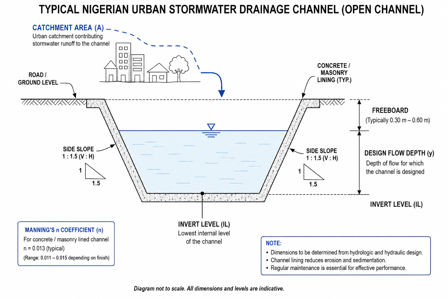
Annotated cross-section diagram of a rectangular stormwater drainage channel showing hydraulic design parameters”
Placement rationale: Introduces the physical reality of hydraulic structures before the first detailed H2, giving visual context for readers unfamiliar with channel geometry.
Hydraulic engineering sits at the intersection of fluid mechanics, geotechnics, and structural design. Where a structural engineer asks “will this beam carry the load?”, a hydraulic engineer asks “will this channel carry the flow — and what happens when it cannot?” The discipline draws on open channel flow theory, pipe hydraulics, hydrology, sediment transport, and coastal dynamics, often within a single project.
The core governing equations appear repeatedly across all hydraulic engineering examples. Manning’s equation — Q = (1/n) × A × R2/3 × S1/2 — describes flow in open channels, where Q is discharge in m³/s, n is the roughness coefficient, A is the cross-sectional area, R is the hydraulic radius, and S is the bed slope. For a concrete-lined channel, n typically sits at 0.013 to 0.015; for an earthen canal, it rises to 0.025 or higher depending on vegetation.
Bernoulli’s principle governs energy conservation along a streamline: pressure head, velocity head, and elevation head sum to a constant in an ideal, frictionless system. In practice, head losses from friction (Darcy-Weisbach), fittings, and transitions reduce that total, and these losses drive pipe sizing decisions in water supply networks.
The continuity equation — Q = A × V — is elementary but forms the basis of every flow routing calculation. It confirms that what enters a system must leave it, accounting for storage. When a design ignores storage effects during peak events, the result is the kind of downstream flooding seen repeatedly in Lagos during intense rainfall on the Eko Atlantic coastal fringe.
The Regulatory and Standards Framework in Nigeria
Hydraulic design in Nigeria references British Standards as adopted and modified by local practice, supplemented by Federal Ministry of Works guidelines and state-level environmental regulations. BS EN 752 governs sewer and drain systems outside buildings. BS 8007 (now largely superseded by BS EN 1992-3) covers water-retaining structures. The Federal Ministry of Water Resources publishes guidelines for dam design and irrigation schemes under the National Water Resources Master Plan.
COREN-registered engineers are responsible for confirming that hydraulic designs meet minimum safety standards. For dam structures above 15 metres in height, designs must go through a formal dam safety review process. Smaller structures — culverts, roadside drains, service reservoirs — fall under the supervision of state water agencies or local government engineering departments, with variable oversight quality depending on the state.
Engineers working in Lagos must additionally navigate the Lagos State Ministry of Environment guidelines, which specify minimum freeboard requirements and restrict development within defined flood risk zones. Abuja projects reference the FCDA’s physical planning regulations, which include drainage setback requirements. These local overlays sit on top of the national standards and frequently create design constraints that are not immediately obvious from the federal guidelines alone.
Dams and Reservoirs: Nigeria’s Large-Scale Hydraulic Structures
Dams represent the most capital-intensive hydraulic engineering examples in Nigeria, and several have defined the country’s infrastructure landscape for decades. The Kainji Dam on the Niger River, commissioned in 1968, remains the country’s largest hydroelectric facility at 760 MW installed capacity. The Shiroro Dam in Niger State (600 MW) and Jebba Dam (578 MW) form the other pillars of Nigeria’s hydro generation fleet. Beyond power, the Tiga Dam in Kano State irrigates over 30,000 hectares of farmland through the Kano River Irrigation Project.
Key Design Considerations for Embankment Dams
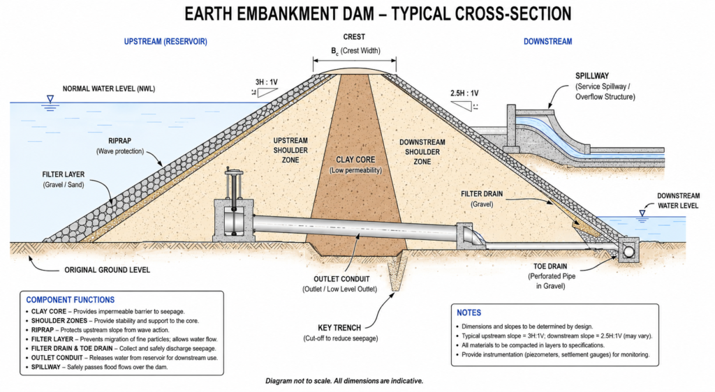
Most Nigerian dams are earth embankment dams — compacted fill structures with an impermeable clay core, upstream and downstream shoulder zones of coarser material, and riprap protection on the upstream face. The design of an embankment dam integrates several engineering disciplines simultaneously.
The spillway is the most hydraulically demanding element. It must pass the design flood — typically the Probable Maximum Flood (PMF) for high-consequence structures, or a return period flood (commonly 1-in-10,000 years for large dams) — without overtopping the embankment. Overtopping of an earthen dam is almost always catastrophic; it initiates rapid erosion and breach. The spillway design uses the broad-crested weir equation: Q = 1.705 × Cd × L × H3/2, where Cd is the discharge coefficient, L is the weir length, and H is the head above the weir crest.
The outlet works — typically a conduit through or around the embankment — must allow controlled drawdown of the reservoir and pass environmental flows downstream. These structures are subject to cavitation if flow velocities exceed approximately 12 m/s in unlined concrete conduits, and their design requires energy dissipation structures (stilling basins, flip buckets) at the exit. Scour protection downstream of any high-velocity discharge is a recurring maintenance issue at Nigerian dam facilities, where post-construction inspection and maintenance programmes have not always been sustained.
Seepage through and beneath the embankment is managed through a system of filters and drains. Piping failure — the internal erosion of fine particles along seepage pathways — has caused more embankment dam failures worldwide than any other mechanism. The particle size criteria for filter compatibility follow Terzaghi’s filter rules, verified against BS EN 13253 for geotextile filters.
Reservoir Routing and Flood Attenuation
A reservoir does not simply store water — it attenuates flood peaks. When a storm generates an inflow hydrograph that rises sharply, the reservoir absorbs that peak and releases it more slowly through the spillway. This reservoir routing calculation uses the continuity equation in discrete time steps: (I₁ + I₂)/2 − (O₁ + O₂)/2 = (S₂ − S₁)/Δt, where I is inflow, O is outflow, S is storage, and Δt is the time step.
The degree of attenuation depends on the ratio of storage volume to the inflow volume. Large reservoirs with significant dead storage relative to the design flood volume attenuate peaks dramatically. Smaller off-stream storage dams — common in irrigation schemes in the Middle Belt states — may provide limited attenuation and require more conservative spillway sizing.
For a deeper technical treatment of the geotechnical aspects that underpin dam embankment design, the geotechnical engineering guide on this site covers soil investigation methods, permeability testing, and seepage analysis in the Nigerian context.
Urban Stormwater Drainage: The Most Frequent Hydraulic Engineering Challenge in Nigeria
Urban drainage is where hydraulic engineering has the most direct impact on Nigerian lives. Flooding in Lagos, Benin City, Warri, and Onitsha is not primarily a function of rainfall intensity — it is a function of drainage systems that were either never built to adequate capacity, have silted up, or have been obstructed by encroachment and waste dumping. Addressing it requires applying hydraulic engineering examples from first principles, not assuming that historical design standards remain adequate.
The design sequence for an urban drainage network begins with catchment hydrology. The Rational Method — Q = CiA/360 (with Q in m³/s, i in mm/hr, and A in hectares) — remains the most widely used approach for urban catchments below approximately 80 hectares in Nigeria. The runoff coefficient C reflects land use: 0.70 to 0.95 for dense urban areas, 0.25 to 0.40 for open parkland. As Lagos densifies, the effective C for many catchments has increased significantly from the values used in original drainage master plans, partly explaining why infrastructure designed in the 1970s and 1980s now floods under storms that should be within its design capacity.
For larger catchments, time-area methods or unit hydrograph approaches provide better representation of the catchment’s travel time characteristics. The time of concentration — the time for runoff from the most remote point of the catchment to reach the design point — governs the critical storm duration. A shorter concentration time means a higher peak intensity for the same return period storm, driving up the design discharge.
Channel sizing follows from the discharge calculation. For rectangular concrete-lined channels, a typical side slope of 90° (vertical walls) maximises the hydraulic radius for a given cross-section. Trapezoidal channels with 1:1 or 1:1.5 side slopes are preferred in earthen or weakly cemented formations because they resist sloughing. A minimum freeboard of 300 mm is standard practice for drainage channels up to 1.0 m depth; 500 mm is more appropriate for channels carrying flows above 2.0 m³/s.
Culverts — pipe or box structures that carry drainage beneath roads or embankments — are sized using inlet or outlet control hydraulics. Under inlet control, the culvert entrance limits flow and the barrel flows partly full; capacity is governed by the headwater-to-diameter ratio. Under outlet control, the tailwater level or friction losses along the barrel limit capacity. Many drainage failures occur because culverts were designed for inlet control but operate under outlet control conditions due to high tailwater, reducing their actual capacity significantly below the design figure.
The fundamentals of hydraulic engineering — including pressure flow, open channel theory, and hydraulic grade lines — underpin all of these drainage calculations and are worth revisiting before designing any significant drainage scheme.
Water Supply Networks and Irrigation Systems
Water supply networks are closed-system hydraulic engineering examples that differ fundamentally from open-channel drainage. Flow is driven by pressure rather than gravity slope, and the design goal is to maintain adequate pressure at all demand nodes simultaneously — including during peak demand periods and firefighting scenarios.
Distribution networks are analysed using the Hardy Cross method or, in modern practice, software tools such as EPANET (developed by the US EPA but freely available and widely used internationally). The analysis balances two conditions at every node: the sum of flows entering and leaving must equal demand (continuity), and the head loss around every loop must sum to zero (energy conservation). Head losses in pipes follow the Hazen-Williams equation — V = 0.8492 × C × R0.63 × S0.54 — with the Hazen-Williams C coefficient reflecting pipe material: 140–150 for new uPVC, 100–110 for aged cast iron, 80–90 for severely tuberculated pipes.
Nigeria’s urban water supply infrastructure suffers from two simultaneous problems: aged distribution networks with high physical losses (non-revenue water frequently exceeds 50% in major Nigerian cities according to World Bank assessments of the sector), and insufficient bulk water treatment capacity. Hydraulic engineers working on rehabilitation projects must account for the interaction between pressure management — reducing pressures to cut leakage — and minimum pressure requirements at consumer connections. Pressure reduction valves (PRVs) zone the network and allow differential pressure management without interrupting supply.
Irrigation hydraulics centres on conveyance efficiency. A lined canal delivers water with a conveyance efficiency of 90–95%; an unlined earthen canal in permeable soils may lose 40–60% to seepage before the water reaches the field. The Kano River Irrigation Project and the Bakolori Irrigation Scheme in Zamfara both face ongoing challenges with seepage losses from unlined secondary and tertiary canals, reducing the irrigated area that can be served from the designed reservoir yield. Canal lining with concrete or compacted clay improves efficiency but significantly increases capital cost — typically by a factor of three to five over earthen canals.
For engineers managing water infrastructure contracts, the water resources guide on this site covers demand forecasting, catchment yield analysis, and the Nigerian legislative framework governing water abstraction rights.
Common Hydraulic Engineering Failures and What Drives Them
Reviewing what goes wrong in hydraulic projects is as instructive as studying what works. Failures in this discipline tend to be consequential — flooding displaces communities, dam breaches destroy lives, and failed drainage causes structural damage to roads and buildings. Understanding the failure modes helps engineers build in the right safeguards at design stage.
The most common failure category in Nigerian hydraulic infrastructure is under-design for current conditions. Drainage infrastructure designed in the 1960s to 1980s used rainfall intensity data from that period and assumed land use patterns that no longer exist. Catchments that were partially agricultural are now fully urbanised, and imperviousness has increased sharply. The design discharges used at the time may be 30–50% below the flows those systems now need to carry. Without periodic hydraulic reassessment, the infrastructure appears to function normally until an extreme event — and then fails dramatically.
The second major failure mode is maintenance neglect. Silting of channels and culverts is predictable and quantifiable using sediment transport equations. A 200 mm depth of silt in a 1.0 m deep drainage channel reduces its hydraulic cross-section by 20% and, through the effect on hydraulic radius, reduces capacity by more than 20%. Vegetation growth in earthen channels raises Manning’s n and cuts capacity further. Design documents rarely include a maintenance schedule, and clients rarely fund one — this gap between hydraulic design and asset management is a system-level failure that COREN-registered engineers have an obligation to flag.
Third is hydraulic grade line errors in pipe networks. When junctions are designed without proper accounting for local head losses — bends, tee-junctions, transitions — the actual pressure at delivery points falls below the minimum required (typically 7 metres residual head at consumer connections for water supply). This produces intermittent supply and forces consumers to use booster pumps, increasing system pressures unpredictably and accelerating pipe failures.
Finally, scour at bridge piers and abutments is a persistent problem on Nigerian road infrastructure. The hydraulic design of bridge waterway openings requires estimation of the general scour depth using the HEC-18 methodology (adapted for local conditions and cross-referenced with BS 5400 Part 2 for flow estimation). Bridges that constrict the natural floodway by more than 20% of its width create significant contraction scour during flood events. Several bridge collapses on federal highways in Nigeria in the past decade have been attributed to scour that was not adequately designed for.
Engineers reviewing bridge or culvert designs can cross-reference the structural loading considerations in the structural engineering guide, which addresses how hydraulic scour depth affects foundation design requirements.

Best Practices for Hydraulic Engineering Design in Nigeria
The following practices separate hydraulic designs that perform over their full service life from those that fail within the first decade. Apply them at design stage — retrofitting is always more expensive.
Use current and locally calibrated hydrological data. Rainfall intensity-duration-frequency (IDF) curves derived from Nigerian Meteorological Agency (NiMet) records should be the primary source for design storms. Where gauge records are sparse or short, regional frequency analysis using index flood methods provides more reliable estimates than applying UK or US IDF curves without adjustment. The National Root Mean Square Error (RMSE) for regionalised flood frequency estimates in Nigeria’s Southwest zone is significantly higher than for regions with dense gauge networks — build conservatism into your return period selection to account for this uncertainty.
Size for the 1-in-100 year event with climate change uplift. Nigerian federal and Lagos state guidelines for major drainage infrastructure specify a 1-in-100 year design return period as the minimum for trunk drainage. Given observed trends in extreme rainfall intensity across southern Nigeria, applying a 10–20% uplift on design discharges is prudent and increasingly expected by informed clients and regulators. Do not design to the minimum standard when the consequences of exceedance are high.
Check both inlet and outlet control for all culverts. Design the culvert for the critical controlling condition — whichever gives the lower capacity — not just the inlet control case. Verify that downstream channel capacity is sufficient to carry the culvert discharge without creating backwater that raises the tailwater above your design assumption.
Specify maintenance access in the design drawings. Access ramps to drainage channels, rodding eyes on pipe systems, silt traps at culvert inlets, and removable trash screens all require specification and detailing. If you do not draw them, they will not be built. If they are not built, the hydraulic design will degrade faster than your calculations assumed.
Document your design assumptions explicitly. State the Manning’s n values you used and why. State the catchment area, the time of concentration method, and the IDF source. Future engineers — and future courts, in the event of a flood damage claim — need to understand the basis of your design. This is a professional obligation under COREN’s Code of Conduct, not just good practice.
Conduct a hydraulic check on any existing downstream infrastructure before designing an upstream system that will increase peak flows. Improving drainage in one subcatchment without checking the capacity of the receiving drain downstream simply moves the flood problem rather than solving it. This systems perspective is the difference between a drainage design and a drainage solution.
These principles apply equally to irrigation canal design, pipeline network design, and coastal protection works. The specifics of each hydraulic engineering example change; the discipline of systematic design, conservative assumptions, and documented reasoning does not. For guidance on applying these principles within a structured project delivery framework, the project delivery guide covers how hydraulic design interfaces with procurement, programming, and site supervision.
Frequently Asked Questions About Hydraulic Engineering
Q: What is hydraulic engineering in civil engineering?
A: Hydraulic engineering is the branch of civil engineering that designs and manages infrastructure to control, convey, and store water. It applies fluid mechanics principles — open channel flow, pipe hydraulics, hydrology, and sediment transport — to structures such as dams, drainage networks, irrigation canals, water supply systems, and coastal protection works. In Nigeria, it is particularly relevant to flood management, rural water supply, and large-scale irrigation schemes.
Q: What are examples of hydraulic engineering projects in Nigeria?
A: Nigeria’s hydraulic engineering examples include the Kainji, Shiroro, and Jebba hydroelectric dams on the Niger River; the Kano River Irrigation Project serving over 30,000 hectares; the Lagos State drainage master plan infrastructure; the Oyan Dam water supply scheme serving Ogun and Lagos states; and numerous rural water supply projects under state rural water and sanitation agencies (RUWASSAs). Bridge waterway design on federal highways is also a significant hydraulic engineering activity.
Q: What is Manning’s equation and when is it used in hydraulic engineering?
A: Manning’s equation — Q = (1/n) × A × R2/3 × S1/2 — calculates the flow rate in an open channel based on its cross-sectional area, hydraulic radius, bed slope, and roughness coefficient. It is the primary tool for sizing drainage channels, irrigation canals, and any structure with free surface flow. The roughness coefficient n varies from 0.013 for smooth concrete to 0.035 for rough earthen channels with vegetation, and selecting the right value for site conditions is one of the most consequential judgement calls in channel design.
Q: What is the difference between hydrological and hydraulic design?
A: Hydrological design determines how much water arrives at a point — it translates rainfall into flow rates using methods like the Rational Method or unit hydrograph analysis, accounting for catchment area, land use, and storm duration. Hydraulic design then takes that flow rate and works out how to convey or store it — sizing channels, pipes, culverts, spillways, and reservoirs. Both are needed for any drainage or water management project; errors in the hydrological step compound through the hydraulic design.
Q: How much does a hydraulic engineering study cost in Nigeria?
A: Costs depend heavily on scope. A hydrological and hydraulic (H&H) study for a small urban drainage scheme (catchment below 50 hectares) typically ranges from ₦1.5 million to ₦4 million. A full feasibility study for a medium-sized dam or irrigation scheme — including hydrological analysis, dam break modelling, and environmental screening — may cost ₦15 million to ₦60 million or more, depending on data availability and the extent of field investigation required. COREN guidelines specify minimum fee scales for engineering consulting services, which provide a floor for budget estimation.
Q: What software do hydraulic engineers use in Nigeria?
A: The most common tools are EPANET for water distribution network analysis, HEC-HMS and HEC-RAS (developed by the US Army Corps of Engineers, widely adopted internationally) for hydrological modelling and river hydraulics, SWMM for urban stormwater modelling, and AutoCAD Civil 3D for drainage design and grading. MIKE FLOOD and InfoWorks ICM are used on larger urban flood modelling projects where budget allows. Spreadsheet-based calculations using Manning’s and Rational Method remain standard for smaller drainage designs in everyday practice.
The hydraulic engineering examples covered in this article — dams and reservoirs, urban stormwater drainage, water supply networks, irrigation systems, bridge waterway design, and coastal protection — share a common foundation: fluid mechanics principles applied to real infrastructure with real consequences for real communities.
Nigeria’s hydraulic challenges are not generic. They reflect specific rainfall regimes, specific soil and geological conditions, decades of under-investment in drainage and water supply infrastructure, and the pressure of rapid urbanisation on systems not designed to accommodate it. Engineers who work here must combine theoretical rigour with hard-won local knowledge — understanding why the Manning’s n for a Lagos drainage channel in service for five years is probably higher than the design assumed, or why the design flood for a structure in the Niger Delta needs to account for tidal backwater as well as upstream hydrology.
Getting hydraulic engineering right means fewer flooded roads, fewer failed bridges, more reliable water supply, and more productive irrigated agriculture. If you are working on a project that involves hydraulic design — from a simple culvert to a major reservoir — and you want independent technical review or full design services, StruviaCore’s hydraulic engineering team is available to support projects at any stage, from feasibility through to construction supervision.
Leave a Reply