
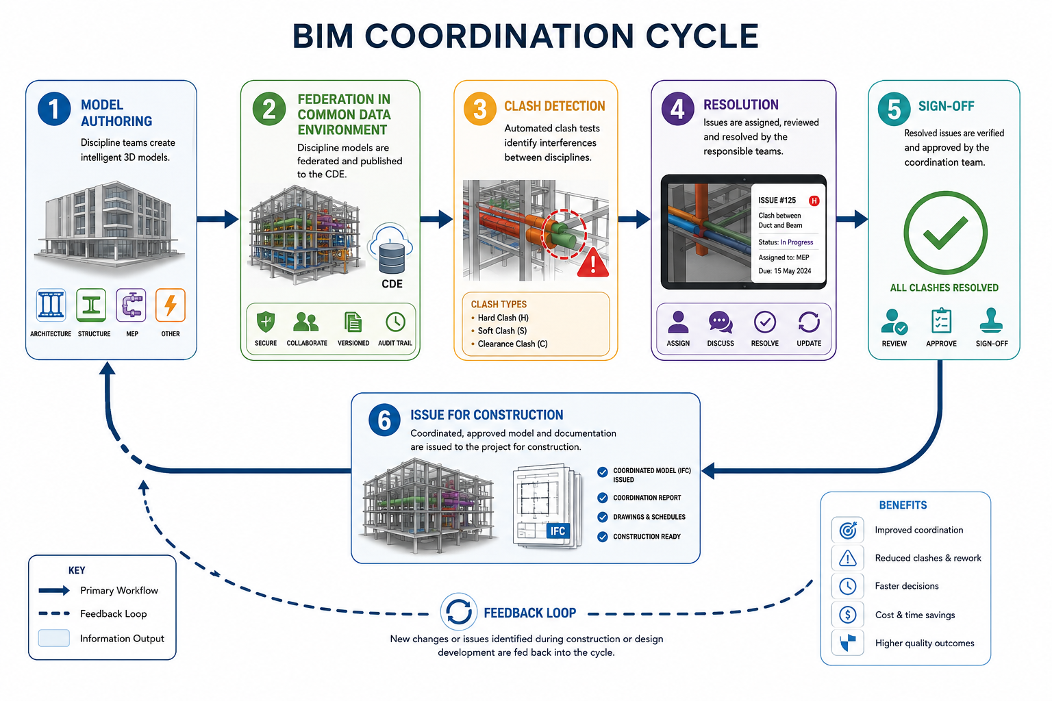
A structural team in Lagos issues a reinforced concrete drawing package. Three weeks later, the MEP contractor discovers a 300mm chilled water riser clashing with a transfer beam on the fourth floor. The clash was visible in the model the entire time — nobody was looking at the model together. This is the scenario that BIM best practices exist to prevent. Building Information Modelling is not a software licence; it is a set of disciplined workflows that determine whether your model actually reduces risk on site or just sits in a folder looking impressive. This article covers what BIM best practices mean in practice, the technical workflows that make coordination work, and the checklist you need before your next model handover.
BIM Best Practices: Quick Answer
BIM best practices are the standardised workflows — common data environments, agreed Levels of Development, clash detection cycles, and clear model ownership — that keep a Building Information Model accurate and usable across disciplines. Following ISO 19650 principles, teams update models on a fixed schedule, resolve clashes before issue, and assign a single source of truth for every element.
What BIM Best Practices Actually Mean on a Live Project
Building Information Modelling is the process of creating and managing a digital representation of a structure’s physical and functional characteristics throughout design, construction, and operation. On paper, that sounds like a documentation exercise. On a live project, it is a coordination discipline that touches contracts, staffing, and site sequencing. A structural engineer working in Revit without agreed protocols is not doing BIM — they are drawing in 3D. The difference between the two is best practice: rules for how, when, and by whom the model gets updated.
Most disputes over BIM value come down to unclear ownership. Who owns the architectural grid? Who is responsible when a column moves 150mm during a design freeze and nobody tells the structural team? BIM best practices solve this through a defined Common Data Environment (CDE) — a single, controlled repository where every discipline publishes and retrieves model data. Without a CDE, teams email IFC files back and forth, and by week six nobody knows which version is current.
Model Ownership and the Common Data Environment
A CDE structured according to ISO 19650 — the international standard for managing information over the lifecycle of a built asset — organises files into four states: Work in Progress, Shared, Published, and Archived. A model only moves from Work in Progress to Shared once it passes an internal quality check. This single rule eliminates most of the “which version is correct” arguments that stall coordination meetings. On projects in Nigeria where teams often mix Autodesk BIM 360, Trimble Connect, and shared Dropbox folders, the platform matters less than the discipline of only working from the Shared or Published state.
Assign a BIM Information Manager on every project above a certain scale — typically anything with more than three consultants modelling concurrently. This person does not design anything. Their job is to enforce naming conventions, check federation clashes weekly, and confirm that every discipline is modelling at the agreed Level of Development before issue.
Level of Development vs Level of Detail
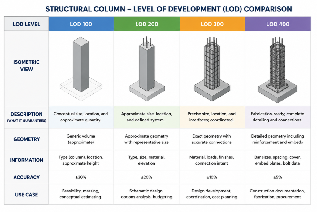
Level of Development (LOD) describes how much you can rely on a model element for a given purpose — not how detailed it looks. An LOD 200 column might display full geometry but only carry approximate size and location; you cannot take a bar bending schedule from it. LOD 350 confirms exact size, quantity, and connection detail suitable for fabrication. Confusing detail with development is a common failure: a beautifully rendered LOD 200 model still cannot be used to order rebar, and treating it as construction-ready causes exactly the kind of clash described in the opening scenario.
Set the required LOD per discipline per project stage in the BIM Execution Plan (BEP) before modelling starts, not after the first coordination clash. A BEP that specifies “LOD 300 for structural steel by RIBA Stage 4” gives every consultant a measurable target rather than a vague aspiration toward accuracy.
Technical BIM Best Practices for Structural and MEP Coordination
Coordination failures rarely come from bad modelling software. They come from inconsistent update cycles and skipped clash reviews. A structural engineer who updates their model every Friday but receives the architectural model every second Tuesday is coordinating against data that is already ten days stale. Fixing this requires a published federation schedule that every discipline signs up to, not a verbal agreement in a kickoff meeting that nobody writes down.
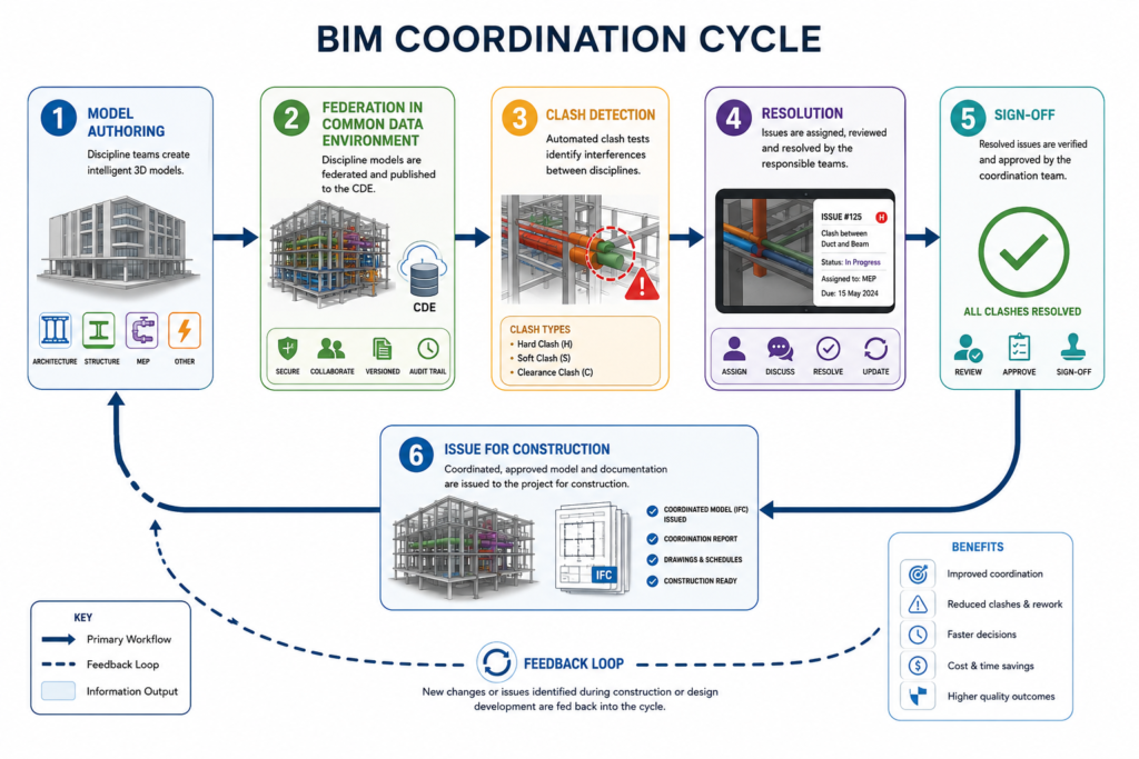
Clash detection tools — Navisworks, Solibri, or BIM 360 Model Coordination — only surface conflicts; they do not resolve them. The best-practice workflow assigns every clash a severity rating, an owner, and a resolution deadline inside the tool itself, then tracks closure the same way a project manager tracks a risk register. Hard clashes (physical overlap) get priority over clearance clashes (insufficient maintenance access), but both need a documented resolution before issue for construction.
Clash Detection Workflows
Run federated clash detection at fixed intervals — weekly during detailed design, twice weekly during the four weeks before issue for construction. Structure the clash matrix by discipline pair: structure-versus-MEP, structure-versus-architecture, MEP-versus-MEP. This prevents a single sprawling clash report with 400 entries that nobody actually reads. On a recent commercial tower coordination exercise in Port Harcourt, splitting the clash matrix this way cut the average clash-to-resolution time from eleven days to four, simply because each discipline lead only reviewed the clashes relevant to their scope.
Parametric Modelling and Rebar Detailing
Parametric modelling ties element geometry to defined rules, so changing a slab thickness automatically updates dependent quantities and connections rather than requiring a manual redraw. For structural work, this matters most in rebar detailing: software like Revit with dynamic reinforcement, or dedicated tools like Tekla Structures, can generate bar bending schedules directly from the model once cover, spacing, and lap lengths are parametrised against the applicable design code. This removes a manual transcription step that is a common source of site-issued schedules not matching the drawn detail.
Regulatory Context: BIM Adoption Across Nigeria, the UK, and the Gulf
BIM mandate maturity varies sharply by region, and best practice includes knowing which rules actually apply to your project. In the UK, BIM Level 2 has been a requirement on centrally procured public projects since 2016, formalised through ISO 19650-1 and 19650-2, which most private clients now reference by default in their employer’s information requirements.
Nigeria does not yet have a nationwide statutory BIM mandate. COREN (the Council for the Regulation of Engineering in Nigeria) has published guidance encouraging digital adoption, and NIS-referenced structural design still governs the underlying engineering regardless of whether the deliverable is a 2D drawing or a federated model. In practice, BIM adoption on Nigerian projects is driven by client sophistication rather than regulation — international developers and multinational EPC contractors typically demand ISO 19650-aligned workflows even where no local mandate requires it.
Gulf markets — the UAE and Saudi Arabia in particular — have moved fastest on mandated BIM for government-funded infrastructure, with Dubai Municipality requiring BIM submissions for buildings above a defined height and floor area since 2014. A structural consultancy working across these markets needs a BEP template flexible enough to scale from a voluntary, client-driven Nigerian commercial project to a mandated Gulf government submission without rebuilding the entire information management approach each time.
The geotechnical layer deserves specific mention here. Soil investigation data — borehole logs, SPT values, groundwater levels — increasingly gets modelled as a georeferenced layer within the federated BIM environment rather than sitting in a separate geotechnical report. For sites in Lagos with variable lateritic and alluvial strata, or reclaimed land along the Lekki axis, embedding this data directly in the model lets the structural team check foundation assumptions against actual investigation points rather than a generalised site-wide bearing capacity figure.
Common BIM Mistakes That Cost Time and Money
The most expensive BIM mistake is modelling in isolation and federating late. Teams that wait until 90% design completion to run their first combined clash detection routinely discover conflicts that require rework across multiple disciplines simultaneously — a far more expensive fix than catching the same clash at 40% design when only one or two elements need moving.
A second recurring problem is inconsistent naming and coordinate systems. If the architectural model sits on a different project base point than the structural model, elements that look aligned in isolated views can be metres apart once federated. Agree the shared coordinate system and project north in the BEP on day one, and confirm it again at every model upload — this single check prevents a category of error that otherwise surfaces only during federation.
- Modelling to impress rather than to inform: highly detailed renders with no underlying data structure look good in a client presentation but cannot generate a quantity take-off or bar schedule.
- Skipping the BEP for “small” projects: a four-storey residential block with three consultants still benefits from a one-page BEP defining LOD, file naming, and update frequency.
- Treating clash reports as a formality: a 200-item clash report that gets exported and filed without individual sign-off provides no actual risk reduction.
- Ignoring version control on shared families: a structural connection family updated by one engineer without notifying the team can silently break dozens of instances across the model.
Cost overruns tied to poor BIM coordination usually trace back to one of these four patterns rather than a software limitation. Fixing the process costs far less than fixing the fallout — rework on a coordination clash discovered on site can run several times the cost of the same fix caught in the model.
A Practical BIM Best Practices Checklist for Project Teams
Use this checklist at project kickoff and again at each major design stage gate. It will not cover every project-specific requirement, but it catches the failures described above before they reach site.
- Confirm a signed BIM Execution Plan exists before any discipline begins modelling, specifying LOD targets by stage.
- Set up a Common Data Environment with clear Work in Progress, Shared, Published, and Archived states.
- Appoint a named BIM Information Manager responsible for federation and clash tracking.
- Agree a shared coordinate system and project base point, confirmed at every upload.
- Schedule federated clash detection on a fixed weekly cadence, moving to twice-weekly in the final month before issue.
- Assign every logged clash an owner and resolution deadline inside the coordination tool itself.
- Embed geotechnical investigation data as a georeferenced layer rather than a standalone PDF report.
- Review naming conventions and shared family version control before each major submission.
You will find that most of these steps cost nothing beyond discipline and a written agreement. The tools already exist on most licensed BIM platforms; what is usually missing is the enforced process around them.

Frequently Asked Questions About BIM
Q: What is BIM in civil engineering?
A: BIM in civil engineering is the practice of creating a shared digital model that carries geometric and non-geometric data — material specifications, load assumptions, quantities — across design, construction, and asset operation. It differs from CAD by linking data to objects rather than producing isolated line drawings, which is why an ISO 19650-compliant model can generate a bar bending schedule, a cost plan, and a clash report from the same source file.
Q: How does BIM clash detection work?
A: Clash detection software such as Navisworks or Solibri federates models from multiple disciplines into one combined view, then runs a geometric check for overlapping elements based on defined tolerance rules. The tool flags hard clashes, where objects physically intersect, and clearance clashes, where minimum maintenance or access space is not met, and outputs a report for the design team to review and resolve.
Q: What are the Level of Development requirements for structural BIM models?
A: Structural models typically progress from LOD 200 at concept stage, showing approximate size and location, to LOD 300 or 350 at detailed design, confirming exact dimensions and connection detail suitable for coordination and fabrication. The exact requirement should be set in the BIM Execution Plan against the project’s RIBA or equivalent design stage, not assumed from software defaults.
Q: How much does implementing BIM cost on a mid-size project?
A: Software licensing for a small structural team typically runs from a few hundred to a few thousand dollars per user annually depending on the platform, but the larger cost is training and the time spent building a functioning Common Data Environment and BEP. On a mid-size commercial project, budgeting for a dedicated BIM Information Manager role, even part-time, usually returns its cost through reduced rework and faster clash resolution.
Q: What is the difference between BIM and 3D CAD?
A: 3D CAD produces geometric shapes with no embedded data beyond visual representation — a column drawn in 3D CAD is just a shape. A BIM element carries attached data such as material grade, load capacity, and cost code, so changing one parameter updates every dependent schedule, quantity, and drawing view automatically across the model.
BIM best practices are not about owning the newest software — they are about the discipline of shared data, agreed development levels, and scheduled coordination that turn a 3D model into a reliable construction tool. The structural team that adopts a clear BEP, a functioning Common Data Environment, and a fixed clash detection cadence will catch the riser-versus-beam conflict at week three of design, not week three of construction. If your current workflow relies on emailed files and informal version tracking, the fixes outlined here are a starting point, not a finished system — refine them against your own project scale and regulatory context. Read our full breakdown of what BIM actually involves or get in touch with StruviaCore to review your current BIM Execution Plan against ISO 19650 requirements.
Leave a Reply