

Buried utilities have delayed, derailed, and in some cases fatally compromised rail infrastructure projects across the UK. When a contractor strikes an uncharted 11kV cable during track drainage excavation, the consequences extend well beyond repair costs — Network Rail possession windows close, compensation events stack up under NEC4, and CDM 2015 investigations follow. The risk is real, and it is entirely manageable when the right processes are in place from the outset.
Best practices for utilities in rail engineering cover the systematic identification, verification, and management of buried and overhead services — gas mains, water mains, electricity cables, telecommunications ducts, and drainage infrastructure — throughout the full project lifecycle. This article sets out the technical and procedural framework that project teams in the UK rail sector should apply, from initial desktop study through to post-construction records. It draws on BS PAS 128:2022, Network Rail’s Governance for Railway Investment Projects (GRIP) process, the New Roads and Street Works Act 1991 (NRSWA), and CDM 2015.
Best practices for utilities in UK rail projects require desktop data gathering from all asset owners, a BS PAS 128:2022-compliant ground investigation combining electromagnetic detection and ground-penetrating radar, independent verification by trial holes before any intrusive works, and formal utility coordination through a Utility Diversion Schedule embedded in the project programme from GRIP Stage 3 onwards.
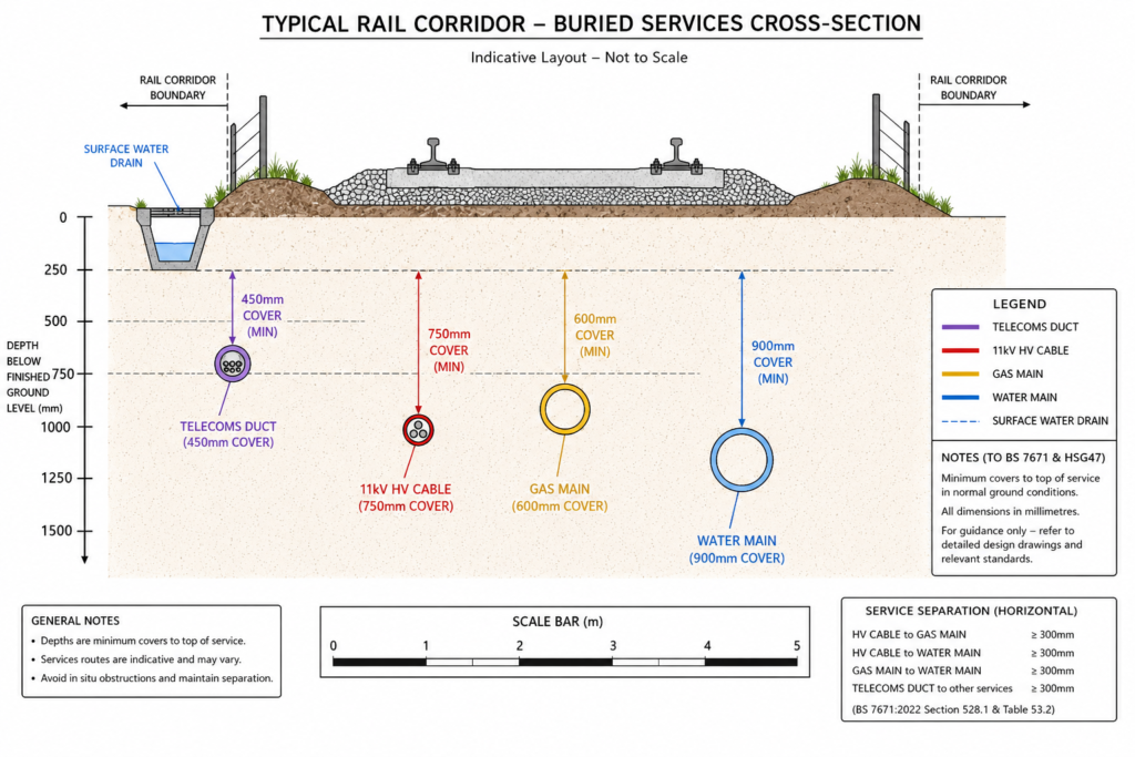
What Utilities Management Means in a Rail Context
Utilities management in rail engineering is the structured process of identifying, recording, coordinating, and protecting all buried and above-ground services that lie within or adjacent to a railway infrastructure corridor. It differs from utilities management on a standard highway or greenfield development in three important ways: the operational sensitivity of the railway means that unplanned service strikes can trigger immediate possessions and safety critical investigations; the linear nature of rail corridors means that services cross the alignment at multiple points, often at skew angles, with limited maintenance access; and the presence of Network Rail-controlled land imposes specific consenting obligations on top of statutory undertaker requirements.
The services that project teams must account for on a typical UK rail scheme include high-voltage electricity cables (including OLE feeder and return cables that may be owned by Network Rail rather than the local DNO), gas mains ranging from low-pressure PE distribution pipes to high-pressure steel transmission lines, water supply and wastewater mains, telecommunications and signalling ducting, and highway drainage outfalls crossing the railway. On urban schemes, particularly those involving existing station areas or level crossings, the density of buried plant can be exceptional — the Crossrail programme identified over 1,000 utility conflicts along its central section alone, requiring a dedicated utility diversion programme worth approximately £700 million.
The Legislative and Standards Framework
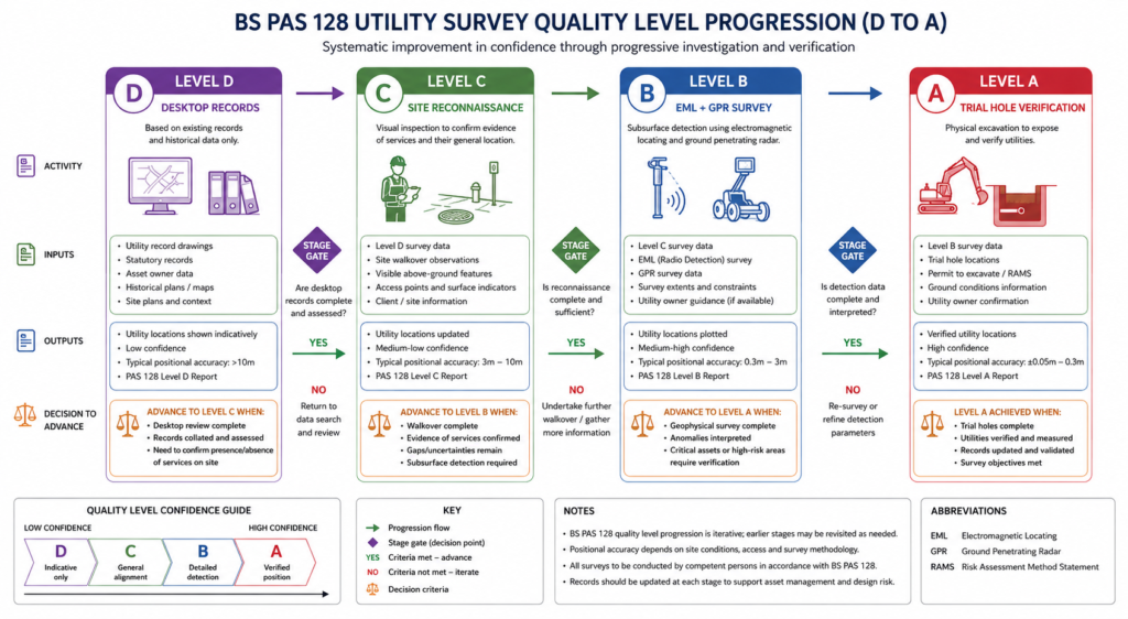
Three instruments govern utilities work on UK rail projects. The New Roads and Street Works Act 1991 and its accompanying Street Works (Qualifications of Supervisors and Operatives) Regulations 1992 set the baseline for work in the public highway. CDM 2015 requires the Principal Designer to consider utility strike risk as a foreseeable construction hazard and mandates that it is addressed in the pre-construction health and safety file. BS PAS 128:2022 — the publicly available specification for utility detection, verification, and location — provides the technical classification system that should be specified in all ground investigation contracts. Quality levels range from D (desktop data only) to A (trial hole verification with direct physical measurement), and specifying the correct quality level for each zone of the site is a design decision, not a procurement shortcut.
Network Rail’s own standards sit on top of these. NR/GN/CIV/0025 (Guidance on Management of Buried Services) and the relevant GRIP stage deliverables define what Network Rail expects in terms of utility survey outputs before intrusive works are authorised. Projects proceeding under a Network Rail Enabling Works Contract or Infrastructure Projects delivery route must demonstrate compliance with these standards as a condition of possession approval.
Who Owns the Risk
Under CDM 2015, the client — whether that is Network Rail, a promoter, or a Transport for the North scheme — carries the primary duty to provide pre-construction information including utility records. The Principal Designer must then assess the adequacy of that information and identify gaps. The Principal Contractor holds the duty to manage residual risk during construction. In practice, this means that responsibility is distributed but not diluted: an inadequate utility survey commissioned at GRIP Stage 3 can generate a CDM enforcement action against the Principal Designer three years later when a contractor strikes a service on site. The duty chain needs to be explicit in the project management plan from the outset.
Survey Methods and Their Correct Application
The technical quality of a utility survey depends on the methods selected, their sequence, and the competence of the operators. No single technology detects all service types in all ground conditions. A technically sound survey programme combines multiple complementary methods, with trial hole verification at any location where the output will inform a design or construction decision.
Electromagnetic Location and Ground-Penetrating Radar
Electromagnetic location (EML) is the workhorse of utility detection for conductive services — metallic pipes, cables, and ducts with metallic content. A signal is applied to the service either by direct connection or by induction, and the operator traces the signal path at the surface. EML is effective to depths of around 3 to 5 metres for most services, with accuracy of ±150mm in plan when conducted by a competent operative following the EUSR Utility Surveying standard. It does not detect non-conductive services such as modern PE gas mains or clay drainage runs unless a duct rod or sonde is inserted.
Ground-penetrating radar (GPR) fills this gap. GPR transmits a high-frequency electromagnetic pulse into the ground and records reflections from subsurface interfaces, including pipes, cables, voids, and formation changes. A 250MHz antenna provides useful penetration to around 3 metres in dry granular soils; penetration reduces significantly in clay-dominant or saturated ground — conditions common on the Midland Main Line corridor and across much of the East Anglian network. Rail corridor GPR surveys can be conducted from a track geometry vehicle during a possesion, which reduces access risk and speeds data collection on operational lines. The output requires specialist interpretation: raw GPR data should never be passed directly to the design team without being processed and annotated by a qualified geophysicist or utility mapping specialist.
For a BS PAS 128 Quality Level B survey — the minimum that most Network Rail scheme sanctioning processes will accept before detailed design — the methodology must combine EML and GPR with a topographic survey overlay, producing a utility record drawing to ±500mm horizontal tolerance and ±250mm depth tolerance at the 90th percentile confidence level.
Trial Holes and Quality Level A Verification
Trial holes — hand-dug or vacuum-excavated exposures of individual services — are the only route to BS PAS 128 Quality Level A verification. They provide confirmed position, depth, diameter, pipe material, and service condition, all of which are necessary before a crossing, diversion, or protection design can be finalised. The position of each trial hole should be determined by the design team in response to the survey data, not left to the contractor to select on convenience grounds. Standard practice is to carry out trial holes at every service crossing within 5 metres of any planned piling, underpinning, or directional drilling operation, and at regular intervals along diversions exceeding 50 metres in length.
Vacuum excavation, using a combination of high-pressure water jetting and vacuum recovery, has largely replaced hand digging for trial holes adjacent to live services. It reduces the risk of direct contact with cables operating at HV, and generates cleaner exposures in confined spaces. However, it requires a pressurised water supply and a licensed disposal route for the arisings, both of which need to be confirmed in the traffic management and environmental management plan before mobilisation.
Understanding how utilities are classified and managed across infrastructure types provides broader context for engineers moving between highway, rail, and marine projects.
Utility Coordination and the Diversion Programme
Technical survey outputs are only useful if they feed a coordinated utility diversion programme. On any rail scheme requiring statutory undertaker involvement, this means engaging asset owners early — at GRIP Stage 3 (Option Selection) at the latest — and maintaining a live Utility Diversion Schedule that is owned by the project manager and updated at every monthly progress review.
The utility diversion process in the UK rail sector follows a broadly consistent sequence. The designer issues a Utility Diversion Request (UDR) to each affected statutory undertaker, including a utility record drawing showing the conflict. The undertaker provides a technical appraisal and a Section 185 quotation under the New Roads and Street Works Act for the cost of the diversion. The promoter accepts the quotation, agrees a programme, and appoints either the undertaker’s own workforce or an approved contractor to carry out the works. Diversions must be complete and signed off — with as-built drawings issued — before the main contractor can break ground in the affected zone. Failing to achieve this sequence is one of the most common causes of programme delay on UK rail projects.
Key coordination risks include long lead times for high-voltage cable diversions: National Grid Electricity Distribution (now National Grid Distribution) and the regional DNOs typically require 52 to 78 weeks from acceptance of quotation to completion of HV diversions exceeding 200 metres. Gas transmission diversions involving steel pipelines can require Cadent or SGN to carry out detailed stress analysis before a diversion route is confirmed, adding a further 12 to 24 weeks to the programme. These lead times need to be incorporated into the GRIP Stage 4 (Single Option Development) programme baseline — not discovered during detailed design.
Coordination with Network Rail’s own signalling and telecoms teams is equally important and often underweighted. Network Rail-owned telecoms cables, including the GSM-R voice radio infrastructure and the fibre backbone that carries ETCS data, are not registered with statutory undertakers and do not appear in utility records requests to external bodies. Their locations must be obtained directly from Network Rail’s Telecom Asset Management system, and any works within 3 metres of a signalling cable corridor require a Signalling Protection Plan approved by the relevant Signalling Maintenance Engineer before works commence.
For teams building their programme structure, the rail engineering guide covers the GRIP stage framework in detail, including the interface between utility diversion workstreams and the main construction programme.
Common Failures and How to Avoid Them
Most utility-related programme failures and safety incidents on UK rail projects trace back to a small number of recurring errors. Recognising them early — before they crystallise into NEC4 compensation events or CDM improvement notices — is the difference between a project that delivers on programme and one that does not.
The first and most frequent failure is inadequate scope definition for the ground investigation contract. A desk study and a Quality Level D records request from the local highway authority are not a utility survey. Teams that treat the statutory records as the final answer — rather than as a starting point for a technical survey — consistently find undocumented services on site. In the Network Rail estate, particularly on lines dating from the Victorian and Edwardian era, it is routine to find cast iron gas mains, earthenware drainage runs, and low-voltage cables that have never been formally recorded in any asset management system. The only way to find them is a physical survey.
The second failure is inadequate zone classification. BS PAS 128 requires the engineer to classify the survey area by risk level and specify the required quality level accordingly. Specifying Quality Level B across an entire alignment without identifying high-risk zones — OLE foundation positions, underbridges, drainage outfalls — leaves areas of genuine conflict inadequately characterised. The quality level specification should be a deliberate engineering decision informed by the desktop study findings.
The third failure is breaking the duty chain under CDM 2015. Where the principal designer hands over a pre-construction information pack that includes utility drawings marked “for information only — not to be used for construction,” but the project does not specify any further survey work in the contractor’s scope, the risk effectively falls to the contractor without adequate information. This is precisely the scenario that CDM 2015 was designed to prevent. The pre-construction information pack must clearly distinguish between confirmed data, indicative data, and areas with no data coverage, and must specify the investigative work required to resolve each gap.
The fourth failure is inadequate as-built record keeping. Post-diversion as-built drawings frequently arrive late, are poorly referenced to the project coordinate system, or contain errors introduced during surveyors’ field-to-drawing transfer. These errors become the next project’s problem — the undocumented service that the next generation of engineers will encounter during a future track renewal or station redevelopment. Every project should mandate that as-built utility drawings are submitted in GIS-compatible format, referenced to OSGB36 National Grid coordinates, within 28 days of completion of each diversion.
Teams looking to build a systematic approach to utility risk should also review the full utilities overview for definitions and asset classification frameworks applicable across infrastructure sectors.
Best Practices Checklist for Rail Utility Management
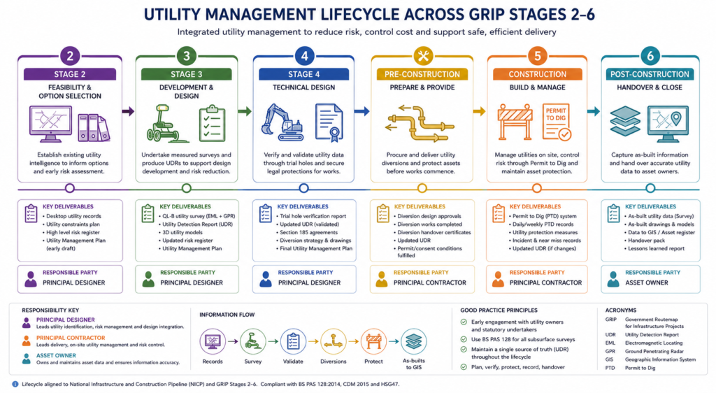
The following sequence covers the minimum standard that a competent rail project team should apply. Each item maps to a recognised standard, duty, or project stage gate. Treat this as a working checklist rather than a summary: every item has a responsible party and a deliverable.
- GRIP Stage 2 / Feasibility: Commission a desktop utility study. Request utility records from all asset owners in the corridor, including Network Rail Telecoms, Environment Agency (for watercourse crossings), and all statutory undertakers within 50 metres of the boundary of influence. Document all responses — including non-responses — in a Utility Records Register.
- GRIP Stage 3 / Option Selection: Specify a BS PAS 128 Quality Level B ground investigation for the full corridor. Define Quality Level A zones at all identified service crossings, proposed piling or foundation locations, and utility diversion tie-in points. Issue Utility Diversion Requests to all conflicting asset owners. Obtain and review Section 185 quotations. Incorporate diversion lead times into the Stage 3 programme.
- GRIP Stage 4 / Single Option Development: Confirm trial hole positions with the design team. Conduct Quality Level A verification at all QLA zones. Finalise diversion designs in coordination with each asset owner. Execute Section 185 agreements. Update the Utility Diversion Schedule with confirmed start dates and completion milestones.
- Pre-Construction / Enabling Works: Verify that all diversions in the main works zone are complete and that as-built drawings have been received and reviewed. Brief the site team on residual utility risk, including the locations of any services that have not been physically verified. Issue site-specific Permit to Dig procedures under the requirements of HS(G)47 (Avoiding Danger from Underground Services) and any Network Rail-specific buried services permit system in use on the project.
- During Construction: Require the contractor to carry out service avoidance scanning with a calibrated EML device before any ground-breaking activity, even in areas previously surveyed. Maintain a live site utility drawing overlaid on the setting-out model. Report any unexpected service encounters immediately to the Principal Designer, update the pre-construction information, and review the CDM risk register.
- Post-Construction: Collect as-built drawings for all installed and diverted services. Convert to GIS format referenced to OSGB36. Submit to the network owner’s asset management system. Update the project health and safety file. Archive originals in the document management system with version control.
The utilities checklist on StruviaCore provides a printable reference version of the key utility management actions for use in project team briefings and stage gate reviews.
For projects where digital survey data management is being considered, the rail infrastructure overview covers the interface between utility asset records and BIM Level 2 data environments, including the use of IFC schema for buried services in Network Rail-sponsored projects.
Frequently Asked Questions About Utilities
Q: What is BS PAS 128 and why does it matter for rail projects in the UK?
A: BS PAS 128:2022 is the British Standard publicly available specification for the detection, verification, and location of underground utilities. It defines four quality levels — D (desktop records), C (site reconnaissance), B (geophysical survey), and A (trial hole verification) — and mandates minimum survey methodologies and positional tolerances for each. On Network Rail projects, compliance with BS PAS 128 is a requirement of the ground investigation sanction process, and specifying the correct quality level for each zone is a Principal Designer responsibility under CDM 2015.
Q: How long does a utility diversion typically take on a UK rail scheme?
A: Lead times vary significantly by service type. Low-voltage electricity and telecommunications diversions of modest scope can be completed in 16 to 26 weeks from acceptance of the Section 185 quotation. High-voltage cable diversions, particularly those involving the transmission network, typically require 52 to 78 weeks. Gas transmission diversions involving high-pressure steel pipelines can run to 24 months when detailed stress analysis and pressure testing are required. These timescales mean that diversion programmes for complex rail schemes must be initiated at GRIP Stage 3, not deferred to detailed design.
Q: What is the difference between a utility survey and a utility records request?
A: A utility records request is a written enquiry to asset owners — typically using the standard request forms required under the New Roads and Street Works Act 1991 — asking them to supply the records they hold for their services in the vicinity of the project. It is a desk exercise and produces only Quality Level D data per BS PAS 128. A utility survey is a physical investigation of the ground using geophysical methods (EML, GPR) and, at Quality Level A, direct trial hole excavation. Records requests are a necessary starting point; they are never sufficient on their own to clear a site for intrusive works.
Q: Who is legally responsible for utility strikes during rail construction?
A: Legal responsibility under CDM 2015 is distributed across the duty holders. The client must provide adequate pre-construction information. The Principal Designer must identify and address gaps in that information. The Principal Contractor must manage residual risk during construction, including operating a Permit to Dig system. An operative who physically strikes a service may also carry personal liability under the Health and Safety at Work Act 1974. In practice, enforcement action following a serious utility strike will examine the adequacy of the survey specification, the quality of the pre-construction information pack, and whether the Permit to Dig procedure was being followed. A project with documented compliance at each stage is in a far stronger position than one that relied on informal assurances.
Q: Do Network Rail’s own assets appear in statutory utility records?
A: No. Network Rail’s signalling cables, OLE feeder cables, return conductor cables, and telecoms infrastructure are not registered with the statutory undertakers and do not appear in standard NRSWA records requests. Their locations must be obtained directly from Network Rail’s Telecom Asset Management and Electrification Asset Management teams. Any works within 3 metres of a signalling cable corridor require a Signalling Protection Plan approved by the relevant Signalling Maintenance Engineer before ground-breaking commences.
Getting Utility Management Right From Day One
Utility management on rail projects is not a procurement function — it is an engineering and programme management discipline that starts at project inception and runs through to post-construction records. The consequences of underinvestment are disproportionate: a £30,000 utility survey carried out properly at GRIP Stage 3 can prevent a £3 million programme delay caused by an uncharted HV cable struck during piling. Best practices for utilities exist not as compliance paperwork but as the practical framework through which engineers manage a risk that is foreseeable, quantifiable, and entirely within their control to mitigate.
The framework is clear: commission desktop studies early, specify BS PAS 128-compliant surveys at the correct quality level for each zone, engage statutory undertakers at GRIP Stage 3, verify by trial hole before any intrusive works, maintain the Permit to Dig discipline throughout construction, and close the project with accurate as-built records in GIS format. None of this is technically complex. All of it requires consistent application, explicit ownership in the project management plan, and a project manager who understands that utility risk deferred is utility risk multiplied.
If your project team needs support with utility survey specification, CDM pre-construction information, or utility coordination management, contact StruviaCore to discuss how we can help you build a technically sound utilities management framework from the earliest project stages.
Leave a Reply