
A 12-storey residential block in Lagos Island begins to settle unevenly six months after handover. Cracks propagate through the ground-floor columns. The structural engineer checks the frame — it’s fine. The problem started below the surface, where fill material of variable compressibility was never properly characterised before construction began. This is geotechnical engineering failure at its most consequential, and it plays out on sites across the world every year.
Geotechnical engineering examples give engineers, project managers, and clients the clearest window into what this discipline actually does — not in abstract terms, but through the decisions that determine whether a structure stands or settles, whether a slope holds or slides, and whether a foundation transfers load safely to competent ground. This article walks through representative geotechnical engineering examples drawn from foundation design, slope stability, ground improvement, retaining systems, and site investigation, with reference to applicable standards and the kind of soil conditions that define project outcomes.
Geotechnical Engineering Examples: Quick Answer
Geotechnical engineering is the branch of civil engineering concerned with the behaviour of earth materials — soils, rock, and groundwater — and their interaction with engineered structures. Real-world examples include pile foundation design in weak alluvial soils, slope stabilisation using ground anchors, preloading of soft clay before construction, and retaining wall design for basement excavations.
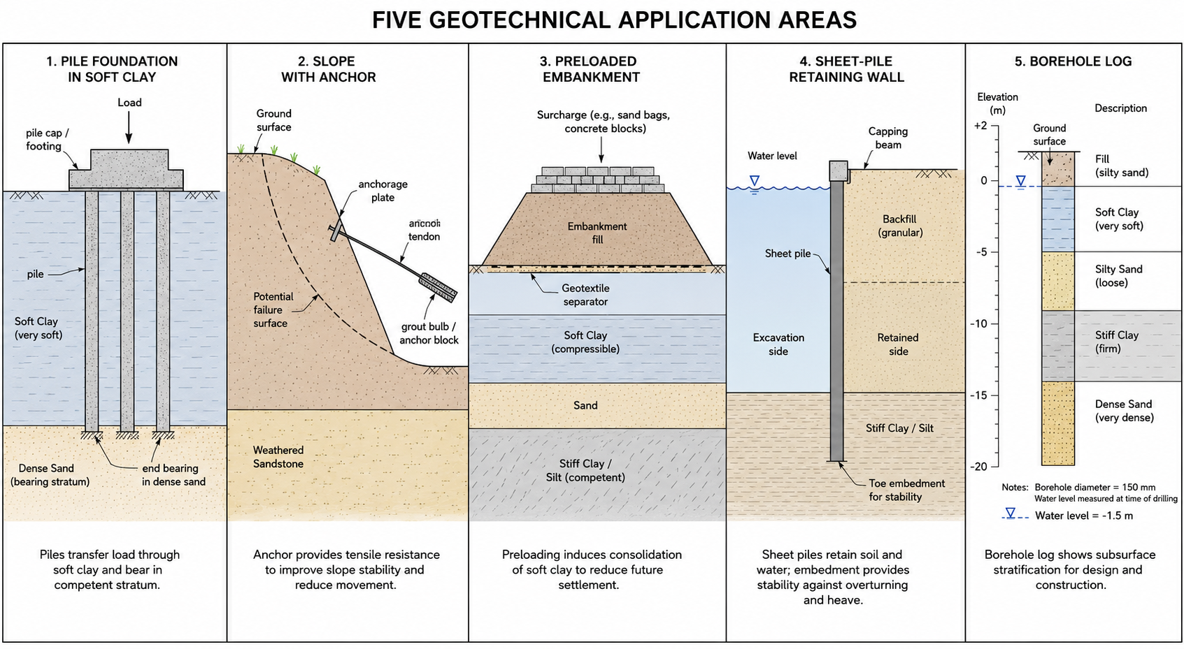
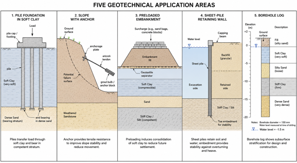
Common geotechnical engineering examples span five core application areas: foundation selection and design (pad, strip, raft, and pile foundations), slope and embankment stability, ground improvement, earth retention, and site investigation. Each example links a soil condition to an engineering decision, with bearing capacity, settlement, shear strength, and groundwater as the governing parameters.
What Geotechnical Engineering Actually Covers
Geotechnical engineering is the branch of civil and structural engineering that analyses how earth materials — soils, rock, and groundwater — behave under load, over time, and in response to construction activity. The discipline sits underneath virtually every built structure: roads, bridges, dams, retaining walls, tunnels, and building foundations all depend on geotechnical assessment to confirm that the ground can safely carry the imposed loads without unacceptable settlement or failure.
The governing parameters in most geotechnical engineering examples are bearing capacity (the maximum load per unit area that soil can support without shear failure), settlement (the downward movement of a structure as soil compresses under load), shear strength (the resistance of a soil mass to sliding or internal failure), and the position and behaviour of the groundwater table. These parameters are not fixed. They change with moisture content, loading history, drainage conditions, and the rate at which loads are applied — which is why geotechnical engineering requires site-specific investigation rather than assumptions drawn from regional averages.
Soil Classification and Its Role in Engineering Decisions
Before any geotechnical design proceeds, the soil must be classified. The Unified Soil Classification System (USCS) and the British Standard BS 5930 provide frameworks for identifying soils by particle size distribution, plasticity, and organic content. In practice, this classification directly informs which foundation type is appropriate, what allowable bearing pressure applies, and whether special treatment is needed.
Poorly graded sands (SP under USCS) drain freely and respond well to spread foundations provided depth is adequate. High-plasticity clays (CH) are problematic — they swell when wet, shrink when dry, and consolidate slowly under load, often driving projects toward pile foundations to bypass the compressible upper strata entirely. Organic soils and peats are almost always bypassed with piles or removed and replaced, as their compression under load is both large and time-dependent.
For an accessible introduction to what this discipline encompasses across project types, the StruviaCore guide to what geotechnical engineering is provides a solid starting point before moving into applied examples.
The Role of Site Investigation
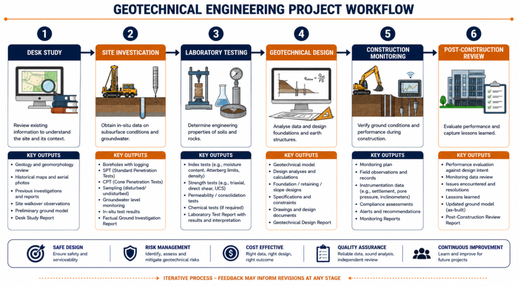
Every credible geotechnical engineering example begins with a site investigation. Desk studies, trial pits, boreholes, Standard Penetration Tests (SPT), Cone Penetration Tests (CPT), and laboratory testing of recovered samples produce the soil profile and strength parameters that govern design. BS 5930:2015 sets out the methodology for site investigation in the UK and forms the basis for equivalent practice in many Commonwealth jurisdictions.
Skimping on site investigation is the single most common source of geotechnical problems on construction projects. A borehole programme that costs £15,000–£40,000 on a typical medium-rise development can prevent remediation costs ten times higher if unexpected conditions emerge during construction. The ground does not negotiate. It simply responds to what is done to it.
Foundation Design: Three Geotechnical Engineering Examples
Foundation design is where most practising engineers encounter geotechnical engineering most directly. The choice between a pad foundation, strip foundation, raft, or pile system is a geotechnical decision as much as a structural one — driven by the soil’s bearing capacity, the groundwater level, the sensitivity of the structure to differential settlement, and the load distribution from the frame above.
Example 1: Pad Foundation on Medium-Dense Sand
A two-storey reinforced concrete-framed office building carries column loads of approximately 600 kN per column. The site investigation reveals medium-dense sand (SPT N-values of 18–25) from 0.6 m below existing ground level, with the groundwater table at 3.5 m depth. The upper 0.6 m consists of made ground.
In this scenario, a square pad foundation bearing at 1.0 m below stripped formation level (to clear the made ground with a 400 mm margin) is appropriate. Using Terzaghi’s bearing capacity equation with appropriate shape and depth factors, and applying a factor of safety of 3.0 to the gross ultimate bearing capacity, a net allowable bearing pressure of 150–180 kPa is achievable on medium-dense sand at this depth. For a 600 kN column load, a pad approximately 2.0 m × 2.0 m satisfies bearing capacity requirements. Settlement analysis using the elastic modulus of medium-dense sand (typically 20–40 MPa) typically shows total settlement well under the 25 mm threshold specified in BS 8004:2015 for most framed structures.
This is a straightforward geotechnical engineering example, but it illustrates the core sequence: characterise the soil, determine allowable bearing pressure, size the foundation to keep contact pressure within limits, and verify that predicted settlement falls within the structural tolerance.
Example 2: Raft Foundation on Soft Clay
Where soil conditions are weaker — soft to firm clays with undrained shear strength (Cu) of 20–40 kPa, as commonly encountered in coastal areas and on floodplain sites — individual pad foundations become impractical. The contact area required to limit bearing pressure to a safe level becomes so large that the pads merge. At that point, a raft foundation is the logical solution.
A raft spreads the total building load across the full footprint, reducing contact pressures to 30–60 kPa for low-to-medium-rise structures. The geotechnical engineer must check two things beyond bearing capacity: immediate (undrained) settlement, which occurs as the clay deforms without drainage; and consolidation settlement, which continues over months or years as excess porewater pressure dissipates. For soft clay with a compression index (Cc) of 0.4 and an initial void ratio of 1.2, consolidation settlement under a net stress increase of 40 kPa at a 3 m thick clay layer can exceed 80 mm — well above acceptable limits for a typical framed structure. This is why soft clay sites often require ground improvement or piles rather than a raft alone.
Example 3: Driven Pile Foundation in Layered Soils
On sites where weak soils extend to considerable depth, pile foundations transfer structural loads to a competent stratum well below the surface. In Lagos, for example, marine clays of low bearing capacity are frequently encountered from 1–2 m depth, overlying dense sands at 15–25 m. Driven precast concrete piles, typically 300 mm × 300 mm or 350 mm × 350 mm in cross-section, are installed to penetrate at least 3 pile diameters into the bearing stratum.
Pile capacity is assessed through a combination of base resistance and shaft friction. In the dense sand stratum, end-bearing resistance can reach 3,000–5,000 kPa at the pile toe. Shaft friction in the clay layers above, though modest at 10–20 kPa per unit area, contributes meaningfully to total capacity on longer piles. A working load of 800–1,200 kN per pile is achievable with 350 mm square driven piles on sites with this stratigraphy, subject to pile load testing per BS EN 12699 to verify design assumptions.
For a deeper treatment of how foundation type selection flows from both soil conditions and structural requirements, see the StruviaCore foundation design guide, which covers the decision matrix across project types.

Slope Stability and Ground Improvement Examples
Not every geotechnical challenge involves a foundation. Slope stability, embankment construction, and ground improvement represent a major share of geotechnical engineering work on infrastructure projects — roads, railways, flood defence embankments, cuttings, and earthworks of all kinds.
Slope Stability: The Bishop Simplified Method in Practice
A road cutting through residual laterite soils on a highway project exposes a slope standing at 1V:1.5H (approximately 34 degrees). The design team needs to verify that the slope is stable under both dry and saturated conditions, because tropical rainfall can raise the water table to near-surface levels within hours of a storm event.
Using the Bishop Simplified Method — a limit equilibrium approach that divides the potential failure mass into vertical slices and applies moment equilibrium about the centre of a circular failure surface — the geotechnical engineer computes a factor of safety (FoS) for the slope. In dry conditions with a laterite friction angle (φ’) of 30° and cohesion (c’) of 15 kPa, the FoS for the 8 m high cutting is calculated at approximately 1.7, comfortably above the minimum of 1.5 required under BS EN 1997-1 (Eurocode 7) for permanent slopes.
Under fully saturated conditions, however, pore water pressures reduce effective stress and the computed FoS drops to 1.2 — marginal. The design response is either to reduce the slope angle to 1V:2H, to install horizontal drainage pipes to lower the saturated zone, or to introduce lime stabilisation of the upper 0.5 m of the slope face to raise the effective cohesion. The choice depends on programme, cost, and the sensitivity of the road alignment to widening the cut footprint.
This is a core geotechnical engineering example in road infrastructure: a calculation that appears acceptable under one drainage condition and unsafe under another, requiring the engineer to design not just for the average condition but for the worst credible one.
Ground Improvement: Preloading with Vertical Drains
Where soft compressible clay underlies a proposed embankment or industrial floor slab, accepting the full consolidation settlement after construction is often impractical. A 4 m thick layer of soft marine clay with a coefficient of consolidation (Cv) of 1.5 m²/year would take over 25 years to reach 90% consolidation under a 3 m embankment surcharge — far beyond any project programme.
Preloading accelerates this process by applying the design load (and often an additional surcharge) before the permanent structure is built, allowing consolidation to occur during the construction period. Installing prefabricated vertical drains (PVDs) at 1.0–1.5 m centres through the soft clay layer reduces the drainage path from the full clay thickness to half the PVD spacing — dropping the time to 90% consolidation from decades to months. After the settlement target is met and confirmed by monitoring, the surcharge is removed, and the structure is built on pre-consolidated, stronger ground.
This technique has been used extensively on large infrastructure projects globally — from airport runways on reclaimed land to industrial estates on estuarine sites. The economics work because preloading with PVDs costs a fraction of the pile foundations that would otherwise be required across a large footprint.
Understanding the challenges that make decisions like this necessary — poor soil conditions, groundwater, time constraints — is covered in detail in the StruviaCore guide to geotechnical engineering challenges.
Retaining Structures: Geotechnical Engineering in Urban Excavations
Urban development regularly requires excavation adjacent to existing structures, services, and roads. Geotechnical engineering governs how that excavation is retained — and how neighbouring structures are protected from movement and settlement induced by stress relief in the ground.
The main retaining structure types are gravity walls (mass concrete or masonry), cantilever walls (reinforced concrete), anchored sheet piles, bored pile walls (contiguous or secant), and diaphragm walls. Each carries a different cost, stiffness, and suitability for the soil and groundwater conditions present.
Consider a 5 m deep basement excavation in a dense urban site, with a busy road 3 m from the excavation edge and an existing 4-storey building 6 m back. The soil profile shows 4 m of firm clay over medium-dense sand. The groundwater table is at 2.5 m depth. A cantilever sheet pile wall would provide limited stiffness and generate lateral movement at the top of the wall of 30–50 mm — enough to cause distress to the existing building. The design solution is an anchored sheet pile with a single row of ground anchors at 1.5 m depth, pre-stressed to 150 kN per anchor at 2.0 m centres. This limits predicted wall deflection to under 15 mm at the anchor level and under 20 mm at the toe — within the tolerable movement threshold for the adjacent building.
The anchor design itself involves a geotechnical assessment of the fixed-length bond zone in the sand stratum. With an average ultimate skin friction of 80 kPa for grouted anchors in medium-dense sand, a 4 m fixed length anchor at 150 mm diameter can develop an ultimate capacity of approximately 150 kN — matching the design load with a factor of safety of 2.0 per BS 8081:2015 (Ground Anchorages). Proof testing of 125% working load and acceptance testing of 100% working load are carried out for each anchor installed.
The geotechnical and structural aspects of basement and retaining wall design interact closely. The foundation design challenges guide on StruviaCore addresses the practical intersection of these two disciplines for basement-level construction.
Common Errors in Geotechnical Engineering Projects
The geotechnical engineering examples above all assume the investigation and design process has been followed competently. In practice, failures and cost overruns on geotechnical elements of projects typically trace to a small number of recurring errors. Knowing what they are is the first step to avoiding them.
Inadequate site investigation scope. A single borehole across a large site, or boreholes that terminate above the founding stratum, leave the design team working with incomplete information. Unexpected soft pockets, perched water tables, or variability in the bearing stratum only reveal themselves during construction — at the worst possible time. The minimum investigation scope should reflect BS 5930:2015 recommendations for borehole spacing and depth relative to the structure type and size.
Applying generic bearing capacity values. Using published presumed bearing values from tables (as permitted under BS 8004 for preliminary sizing) without verification against site-specific SPT data or laboratory testing is appropriate only at the feasibility stage. At detailed design, site-specific parameters must be used. The difference between a presumed bearing capacity of 100 kPa and a site-derived value of 60 kPa can require a complete redesign of the foundation system.
Ignoring groundwater variability. Groundwater levels recorded during a summer investigation may be 1.5–2.0 m lower than peak winter levels on sites in temperate climates, or lower than levels during heavy rainfall in tropical zones. Design must use the highest anticipated groundwater level, not the level at the time of investigation. Failure to account for this has caused unexpected uplift on basement slabs and loss of effective stress in anchor bond zones on multiple documented projects.
Underestimating consolidation settlement timescales. Settlement calculations are often checked against the final magnitude but not the time to reach that settlement. A structure founded on soft clay that settles 60 mm over 30 years may be acceptable for a warehouse but catastrophic for a hospital or precision manufacturing facility where even 5 mm of differential settlement within a short period causes operational problems.
Late engagement of the geotechnical engineer. When the geotechnical specialist joins a project after the structural scheme has been fixed, the design flexibility needed to respond to difficult ground conditions is gone. Geotechnical input should begin at the feasibility stage, inform the site investigation scope, and continue through detailed design.
Best Practices for Geotechnical Engineering Projects
Across the geotechnical engineering examples covered in this article, a pattern of good practice is consistent. These steps apply whether you are the project manager, the client, or the engineer of record.
Start with a thorough desk study. Before a single borehole is sunk, review available geological maps, historical site records, aerial photography, previous site investigation reports, and drainage records. A desk study costs very little and can identify constraints — mine workings, made ground, aggressive groundwater chemistry — that change the investigation strategy entirely.
Scope the investigation to the structure, not the budget. The depth of boreholes should reach at least 1.5 times the foundation width below the founding level for spread foundations, or at least 5 pile diameters below the pile toe for pile design. For structures sensitive to settlement — tall buildings, long-span structures, structures with differential settlement limits below 10 mm — increase borehole depth and frequency accordingly.
Carry out laboratory testing on representative samples. Index properties (Atterberg limits, particle size distribution, moisture content) classify the soil. Strength and compressibility testing (triaxial tests, oedometer tests) provide the design parameters. Relying on SPT N-values alone is insufficient for fine-grained soils where behaviour is governed by cohesion and consolidation rather than relative density.
Apply Eurocode 7 (BS EN 1997-1) systematically. This standard structures geotechnical design around three Design Approaches with specified partial factors for actions and material properties. Using the correct Design Approach for the project’s national annex avoids both underdesign and unnecessary conservatism. The UK National Annex to BS EN 1997-1 specifies Design Approach 1 for most geotechnical design.
Monitor during and after construction. Settlement monitoring using precise levelling, inclinometers in retaining walls, and piezometers to track pore pressure dissipation turns a geotechnical design into a managed, verified outcome rather than an untested prediction. If measurements diverge from predictions, the engineer can respond before damage occurs. This is the principle underlying the Observational Method as defined in BS EN 1997-1, Clause 2.7.
Verify pile capacity through testing. Preliminary pile load tests (static or dynamic — the latter using PDA equipment per ASTM D4945 where accepted by the engineer of record) should precede production piling on all significant pile contracts. They confirm the design pile length, the mobilised capacity at working load, and the factor of safety achieved in the actual soil conditions encountered.
For a structured approach to implementing these practices across a project lifecycle, the StruviaCore geotechnical engineering best practices guide addresses each stage from site investigation brief to post-construction review.
Frequently Asked Questions About Geotechnical Engineering
Q: What are the most common geotechnical engineering examples in building construction?
A: The most common examples are pad foundation design on granular soils, raft foundation design on soft or variable ground, driven or bored pile foundation design where weak soils extend to depth, and slope stability analysis for cuttings and embankments. In urban development, retaining wall design for basement excavations — including anchored sheet piles and secant pile walls — is increasingly common. Each example requires site-specific soil data from a ground investigation before design can proceed.
Q: How does geotechnical engineering differ from structural engineering?
A: Structural engineering analyses the behaviour of constructed elements — beams, columns, slabs, and frames — under applied loads. Geotechnical engineering analyses the behaviour of the ground that receives those loads. In practice, the two disciplines overlap at the foundation level: the geotechnical engineer determines the soil’s bearing capacity and acceptable settlement, and the structural engineer sizes the foundation to transfer the building loads within those limits. Both BS EN 1997-1 (Eurocode 7) and BS EN 1992-1-1 (Eurocode 2) must be applied together for reinforced concrete foundations.
Q: What is the standard for geotechnical design in the UK and internationally?
A: The primary standard is BS EN 1997-1:2004 (Eurocode 7: Geotechnical Design — Part 1: General Rules), used with the relevant national annex. Site investigation is governed by BS 5930:2015 (Code of Practice for Ground Investigations). Foundation-specific guidance appears in BS 8004:2015 (Code of Practice for Foundations) and BS EN 12699 (Execution of Special Geotechnical Works — Displacement Piles). Ground anchorage design follows BS 8081:2015. Many countries outside Europe adopt these standards directly or adapt them into national codes.
Q: How much does a geotechnical site investigation cost?
A: Site investigation costs vary with the number of boreholes, their depth, the testing programme, and the site access conditions. For a small residential development of up to five units, a basic investigation — two or three cable percussion boreholes to 6–8 m depth with SPT testing and a small laboratory suite — typically costs £8,000–£20,000 in the UK. For a medium-rise commercial building requiring six to eight boreholes to 20 m depth with full laboratory testing, costs of £35,000–£80,000 are typical. Specialist techniques such as CPT, pressuremeter testing, or geophysics add further cost but often provide data quality that reduces uncertainty in the design — and reduces the contingency needed in foundation cost estimates.
Q: What is the difference between bearing capacity failure and settlement failure in geotechnical engineering?
A: Bearing capacity failure is a shear failure: the soil beneath the foundation yields and the foundation punches into the ground, typically causing sudden and catastrophic structural damage. Settlement failure is a deformation limit: the soil compresses under load and the structure moves downward, either uniformly (tolerable in most cases) or differentially (potentially damaging to frame connections, cladding, and services). Most modern geotechnical designs are governed by settlement limits rather than bearing capacity — soils with adequate bearing capacity can still produce unacceptable settlement, particularly in clay soils subject to long-term consolidation.
Applying Geotechnical Engineering Examples to Your Project
The examples in this article — pad foundations on sand, rafts on soft clay, driven piles through layered profiles, slope stability in laterites, anchored retaining walls in urban excavations, and preloading with vertical drains — represent the most common scenarios engineers face. None of them is exotic. All of them require site-specific data, a systematic design process, and the right choice of standard to apply.
Geotechnical engineering examples also illustrate a broader truth: the ground rewards preparation and penalises assumption. The engineer who invests in a thorough site investigation, applies Eurocode 7 rigorously, and monitors the structure through construction delivers a project that performs as designed. The engineer who cuts corners on ground investigation or relies on presumed values without verification discovers the problem at the worst possible moment — after the concrete is poured.
StruviaCore provides geotechnical engineering services across the full project lifecycle, from site investigation brief and interpretation through to detailed foundation design, retaining structure design, and construction-stage monitoring. If your project involves complex ground conditions, basement construction, or a site where previous investigation is limited, contact the StruviaCore team to discuss how geotechnical input can be structured from day one — before the ground has a chance to surprise you.
Leave a Reply